Air flue soot dust granule visual sense sampling system and monitoring method

A sampling system, smoke and dust technology, applied in the direction of measuring devices, material analysis through optical means, instruments, etc., can solve the problem of lack of image acquisition and monitoring of smoke dust particles in the flue

Inactive Publication Date: 2008-11-19
UNIV OF SHANGHAI FOR SCI & TECH
View PDF0 Cites 16 Cited by
  • Summary
  • Abstract
  • Description
  • Claims
  • Application Information

AI Technical Summary

Problems solved by technology

[0005] The present invention aims at the problem of the lack of effective flue dust particle image acquisition and monitoring technology, and proposes a visual sampling method for flue dust

Method used


Image

  • Air flue soot dust granule visual sense sampling system and monitoring method

Examples


Embodiment Construction

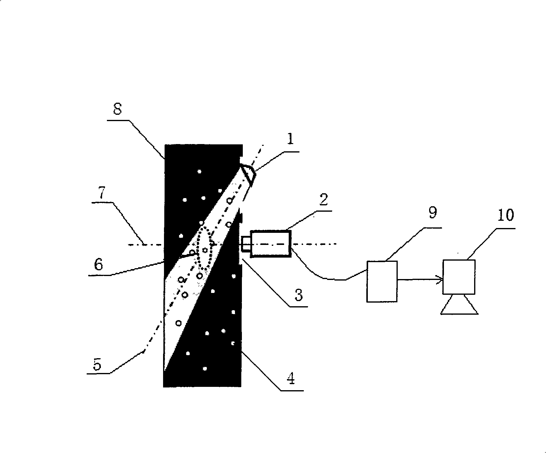
[0009] As shown in Figure 1, the visual sampling method of flue dust particles in the present invention is a schematic diagram. The flue 8 is a dark sealed body, so the image must be collected by a certain light source 1, where a cesium lamp is used to generate uniform parallel light. The image sensor 2 and the illumination light source 1 are installed at the side opening of the smoke discharge channel 8 . The flue here is a part of the flue gas discharge channel (boiler->electrostatic precipitator->flue->chimney), which equivalently reflects the situation of the chimney and the soot particles 4 that are finally discharged into the atmosphere. In order to ensure the ambient temperature conditions in which the image sensor can work normally, a heat-insulating air curtain 3 is installed on the side opening of the flue gas discharge channel corresponding to the image sensor 2. It uses heat-resistant high-transmittance quartz glass to isolate the high temperature inside the flue. ...


PUM


Abstract

The invention relates to a flue dust particle vision sampling system and a monitoring method thereof, wherein, an image sensor and an illumination light source are arranged at the port of a flue gas discharge channel of a flue reflecting conditions of dust particles discharged to the air, and the image sensor acquires the flue dust image information in the flue and enters a computer for processing data through an acquisition card, so the system can realize the on-line real-time detection to flue gas discharge and provide the powerful gist for controlling the atmospheric pollution.

Description

technical field [0001] The invention relates to a detection and sampling system, in particular to a visual sampling system for flue smoke particles. Background technique [0002] With the deepening of human understanding of the hazards of smoke pollution, people have put forward higher requirements for the concentration and particle size of smoke and dust emitted by various pollution sources, and governments of various countries have also formulated various emission standards and regulations accordingly. The control of the total discharge of pollutants is a complex systematic project, and determining the discharge of pollutants is the basis of total control. The measurement of pollutant discharge requires certain detection methods, and the detection results are the most direct and convincing evidence to measure the discharge of each polluting unit. For smoke control, the measured smoke emission concentration can further calculate the overall emission level of emission sourc...

Claims


Application Information

Patent Timeline
IPC IPC(8): G01N15/00G01N21/00G08B21/12
Inventor 戴曙光穆平安金晅宏
Owner UNIV OF SHANGHAI FOR SCI & TECH
Why Eureka
Try Eureka