Antenna device

An antenna device and antenna technology, applied in the direction of antenna, antenna support/mounting device, resonant antenna, etc., can solve the problem that the change of return loss is not very large

Inactive Publication Date: 2008-11-19
莱尔德电子材料(深圳)有限公司
View PDF0 Cites 26 Cited by
  • Summary
  • Abstract
  • Description
  • Claims
  • Application Information

AI Technical Summary

Problems solved by technology

[0014] However, the results show that the change in the return loss obtained in the test of the DCS frequency band is not very large. It can be seen that the effect of adding matching components on the transmission line of the circuit board is limited.

Method used


Image

  • Antenna device
  • Antenna device
  • Antenna device

Examples


no. 1 example

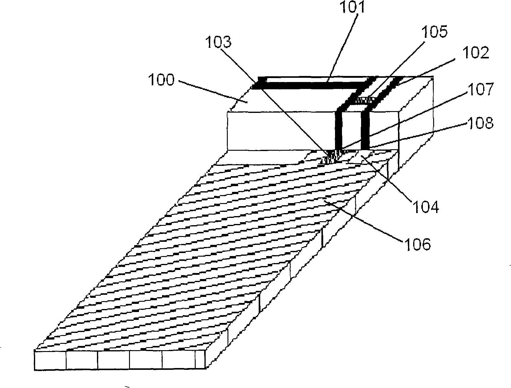
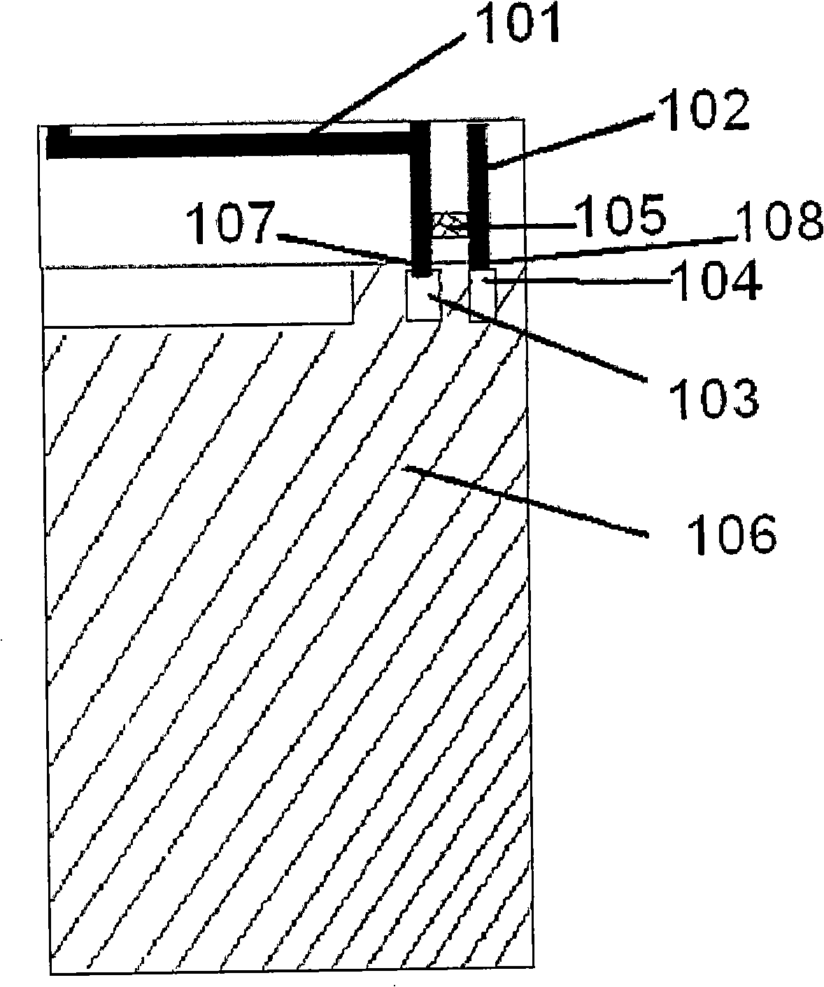
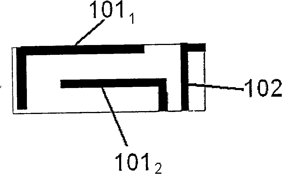
[0037] Figure 1A shows a perspective view of the antenna of the first embodiment of the present invention, Figure 1B shows a top view of the antenna of the first embodiment of the present invention, Figure 1C is a top view of the antenna of the first embodiment of the present invention.

[0038]The antenna of the first embodiment is a built-in antenna used in a mobile phone. The antenna is a five-band antenna. For this antenna, it is required to cover five operating frequency bands from GSM850 / 900 / DCS / PCS to UMTS, which can meet most of the current 3G communication frequency bands.

[0039] Such as Figure 1A As shown, the antenna body 100 is divided into three parts: the main antenna 101 , the parasitic antenna 102 and the matching element 105 . The main antenna 101 and the parasitic antenna 102 constitute an antenna unit. The antenna element can be formed by flexible printed circuit board (flexfilm) technology, constituted as an open rectangular ring. There is a bas...

no. 2 example

[0058] Next, an antenna according to a second embodiment of the present invention will be described. In the following description, detailed descriptions of the same parts as those of the first embodiment are omitted, and attention is paid to different parts.

[0059] Figure 2A with Figure 2B An antenna structure of a second embodiment of the present invention is shown. in Figure 2B A top view of the antenna of the second embodiment of the present invention is shown, and FIG. 2C is a top view of the antenna of the second embodiment.

[0060] The antenna in the second embodiment includes a circuit board 206 , a main antenna 201 , a parasitic antenna 202 , and an inductor 205 as a matching unit. The inductor 205 is connected to the conductor strips of the main antenna 201 and the parasitic antenna 202 . In this embodiment, the main antenna 201 is a conductor strip arranged on the circuit board, and the main antenna 201 is provided with branches 201 as in FIG. 1 1 and 201 ...

no. 3 example

[0063] Next, the antenna structure of the third embodiment of the present invention will be described. In the following description, detailed descriptions of the same parts as those of the first embodiment are omitted, and attention is paid to different parts.

[0064] Figure 3A with Figure 3B An antenna structure of a third embodiment of the present invention is shown. in Figure 3B A top view of the antenna of the third embodiment of the present invention is shown, and FIG. 3C is a top view of the antenna of the third embodiment.

[0065] The antenna of the third embodiment is the same as that of the first embodiment, including a main antenna 301 , a parasitic antenna 302 , and an inductance element 305 as a matching element connected between the main antenna 301 and the parasitic antenna 302 . Different from the first embodiment, in the third embodiment, the main antenna 301 has a feed pin 309 and a ground pin 308, and the feed point 310 and the ground point 303 of th...


PUM


Abstract

The invention provides an antenna device used on wireless equipment. In the purpose of improving the matching of an antenna which is provided with a main antenna element and a parasitic antenna element, the antenna of the invention comprises a main antenna element and a parasitic antenna element; the main antenna element and the parasitic antenna element are separated and a matching unit is arranged therebetween. One end of the matching unit is electrically connected on the conductor band of the main antenna element and the other end is electrically connected on the conductor band of the parasitic antenna element. Optimum antenna characteristic can be obtained by adjusting the position and the numerical value of the matching unit.

Description

technical field [0001] The invention relates to an antenna for a mobile communication terminal, in particular to a built-in antenna suitable for mobile phones and other mobile communication terminals that can cover multiple frequency bands. Background technique [0002] With the rapid development of mobile communication technology and the wide application of mobile wireless systems, mobile phones, as terminal products of mobile communication systems, are moving towards miniaturization, multi-mode (compatible with GSM850 / GSM900 / DCS / PCS / UMTS) and Development in the direction of high performance. [0003] For mobile communication terminal manufacturers, the radio frequency circuit (RF) part, baseband part and digital signal processing part have achieved a high degree of integration so far, which has effectively promoted the miniaturization and integration of mobile communication terminal equipment. Low cost. Only the antenna part, especially the antenna part of the mobile com...

Claims


Application Information

Patent Timeline
Patent Type & Authority Applications(China)
IPC IPC(8): H01Q1/38H01Q9/30H01Q13/08H01Q5/371H01Q5/392
CPCH01Q1/243H01Q5/371H01Q1/38H01Q5/0068H01Q9/42H01Q5/392H01Q5/0058H01Q1/24H01Q9/04
Inventor 张丽霞郭晓娟
Owner 莱尔德电子材料(深圳)有限公司
Why Eureka
Try Eureka