Concentrated winding machine with magnetic slot wedges

A magnetic slot wedge and winding technology, which is applied in windings, manufacturing motor generators, electromechanical devices, etc., can solve the problems of reducing the strength and rigidity of the stator mechanical structure.

Inactive Publication Date: 2008-11-19
GM GLOBAL TECH OPERATIONS LLC
View PDF1 Cites 3 Cited by
  • Summary
  • Abstract
  • Description
  • Claims
  • Application Information

AI Technical Summary

Problems solved by technology

[0009] However, the disadvantage of the stator manufacturing method shown in Figure 3 is that it reduces the strength and rigidity of the stator mechanical structure
Therefore, compared with the segmented stator manufacturing method shown in Figure 1, this method is more likely to cause unwanted vibration and noise

Method used


Image

  • Concentrated winding machine with magnetic slot wedges
  • Concentrated winding machine with magnetic slot wedges
  • Concentrated winding machine with magnetic slot wedges

Examples


Embodiment Construction

[0027] The following detailed description is merely exemplary in nature and does not limit the use of the invention. Furthermore, the invention is not limited by any expressed or implied theory presented in the preceding technical field, background, brief summary, or the following detailed description.

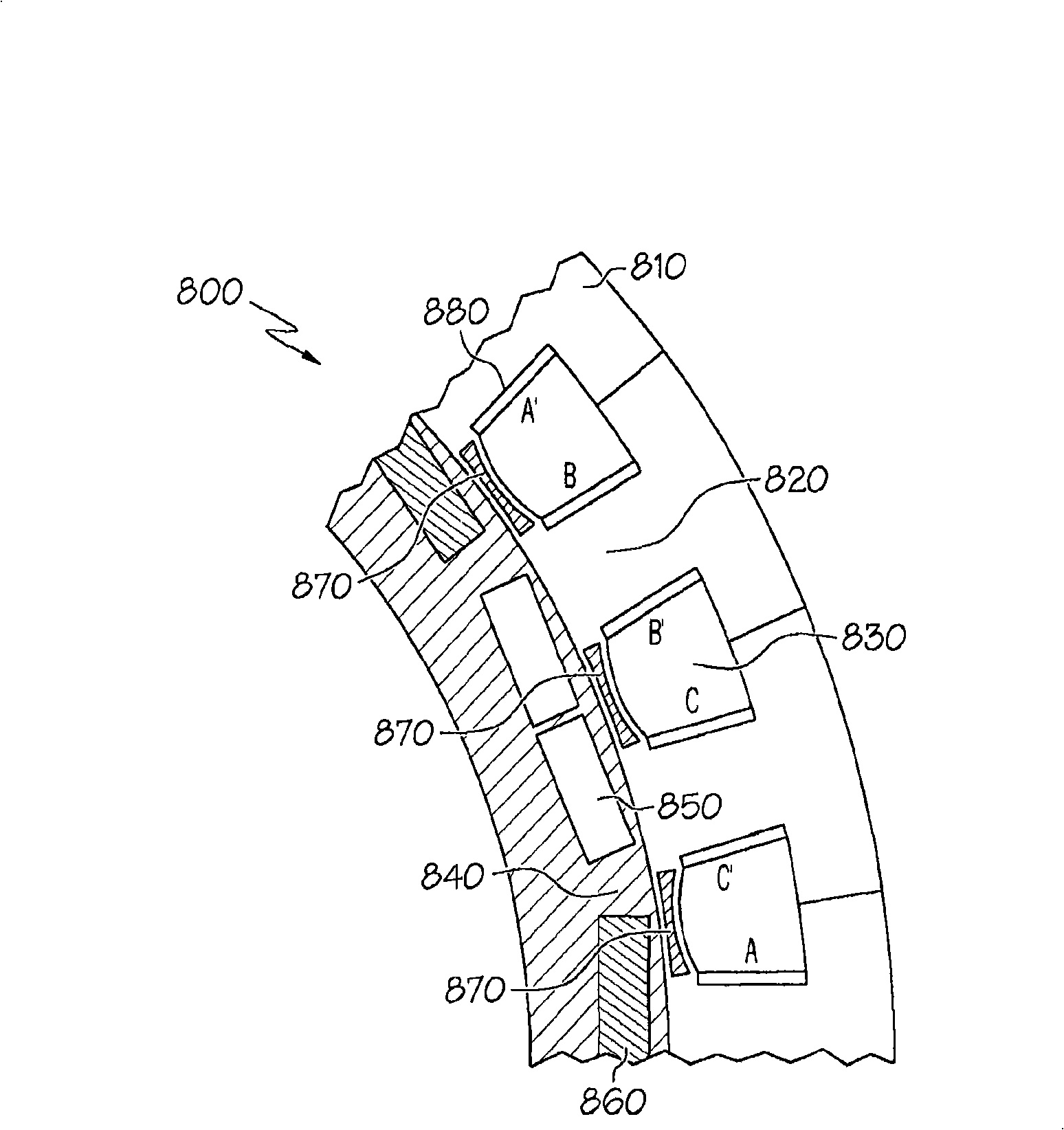
[0028] Figure 4 is a cross-sectional view of stator slot and rotor pole placement in concentrated winding machine portion 800 according to one embodiment. shown in Figure 4 The portion 800 of has a period of 8, ie only 1 / 8 of the entire geometry is shown in the figure.

[0029] In portion 800 , each fixed tooth stator segment 810 has stator teeth 820 with stator slots 830 formed between adjacent stator teeth 820 . Also shown in portion 800 is rotor 840 , rotor north pole 850 and rotor south pole 860 . In total there are 24 stator slots 830 and 16 rotor poles 850, 860, ie a slot to pole ratio of 1.5. For convenience, the Figure 4 The geometry of is called 24-16 geometry. ...


PUM


Abstract

Methods and apparatus are provided for improving operational characteristics of a concentrated winding machine. According to an example embodiment, a method comprises fabricating a magnetic slot wedge that is adapted to be joined to a first stator tooth and a second stator tooth, the first and second stator tooth part of a fixed-tooth stator that does not allow relative movement between the first stator tooth and the second stator tooth.

Description

[0001] Cross references to related applications [0002] This specification is related to US Patent Application entitled "Concentrated Winding Motor with Magnetic Slot Wedges," Attorney No. GP-308954-PTH-CD, which is incorporated herein by reference in its entirety. technical field [0003] This specification relates to electric machines in general, and more particularly to concentrated winding electric machines. Background technique [0004] Motors can have distributed windings or concentrated windings, and the difference between these windings is well known to those skilled in the art. In concentrated winding motors, the stator can be fabricated in sections and then joined to form the complete stator. This is illustrated in FIG. 1 , which is a cross-sectional view of a conventional segmented stator 500 made up of stator segments 510 . Each stator segment comprises tooth bodies 512 and tooth tips 515 . Stator slots 520 between adjacent teeth are formed by the teeth 512 ....

Claims


Application Information

Patent Timeline
Patent Type & Authority Applications(China)
IPC IPC(8): H02K3/487
CPCH02K3/522Y10T29/49009H02K15/066Y10T29/49075H02K3/493H02K15/0018
Inventor K·M·拉曼E·L·凯泽M·D·拉巴
Owner GM GLOBAL TECH OPERATIONS LLC
Why Eureka
Try Eureka