Lifting system

A measurement system and component technology, applied in the field of elevators, can solve problems such as large costs

Inactive Publication Date: 2008-11-19
海德罗器械(升降机)有限及两合公司
View PDF0 Cites 11 Cited by
  • Summary
  • Abstract
  • Description
  • Claims
  • Application Information

AI Technical Summary

Problems solved by technology

Due to the closure of the take-off and landing runway for the time required to rescue the crashed aircraft,

Method used


Image

  • Lifting system
  • Lifting system
  • Lifting system

Examples


Embodiment Construction

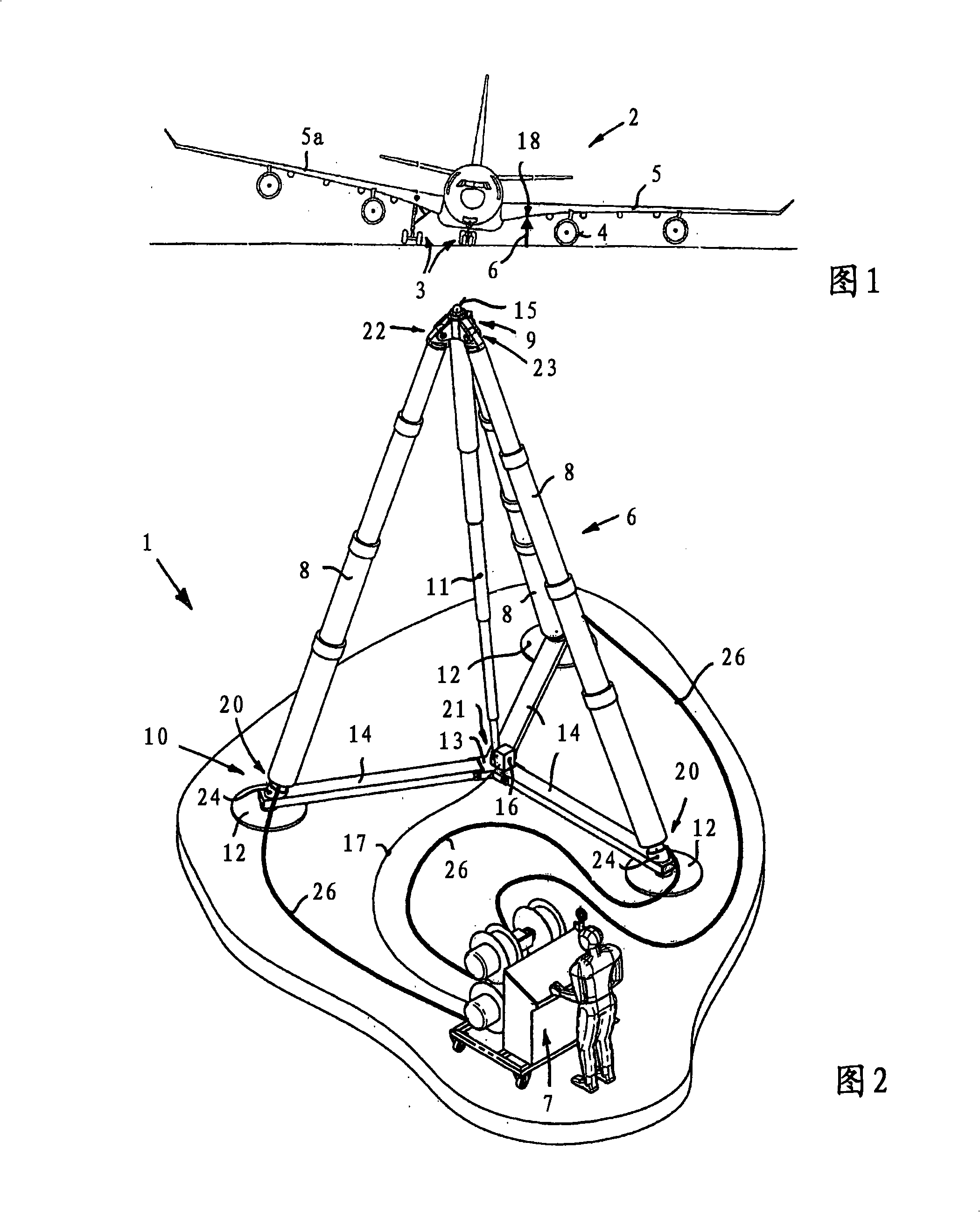
[0037] A lifting system 1 shown in FIG. 2 is used in the exemplary embodiment to rescue a wrecked aircraft 2 as shown in FIG. 1 . In the exemplary embodiment shown, only two of the three undercarriage legs 3 are extended on the aircraft 2 , so that the aircraft rests on a transmission pod 4 on the other side of the retracted undercarriage.

[0038] To rescue the aircraft, it is necessary that the sunken side be raised below the sunken left wing 5 by means of a lift 6 to such an extent that the retracted left undercarriage leg can be extended. The elevator 6 is schematically indicated by an arrow.

[0039] The lift 6 is part of the lifting system 1 shown in FIG. 2 , which in the exemplary embodiment comprises a tripod lift 6 and a control unit 7 .

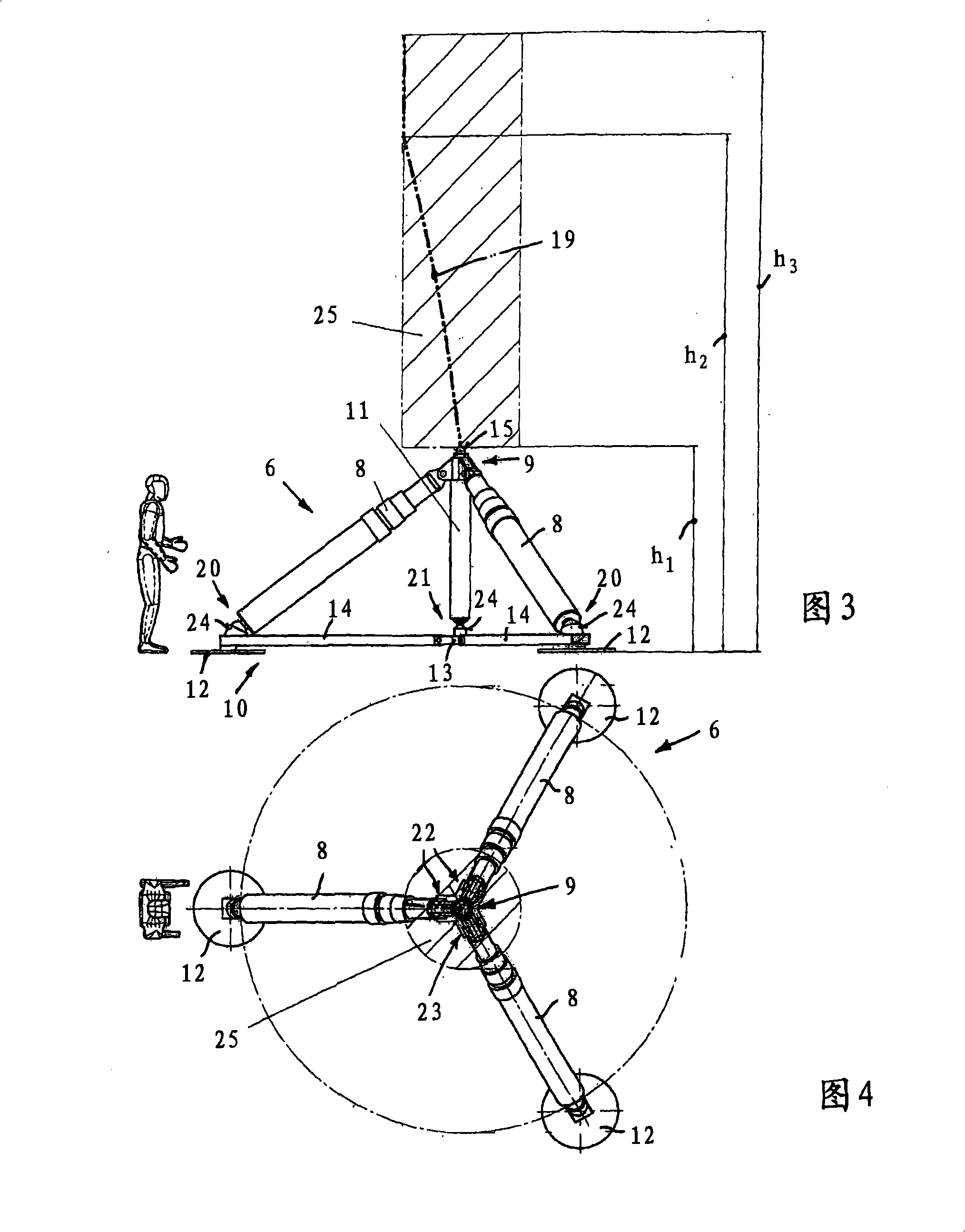
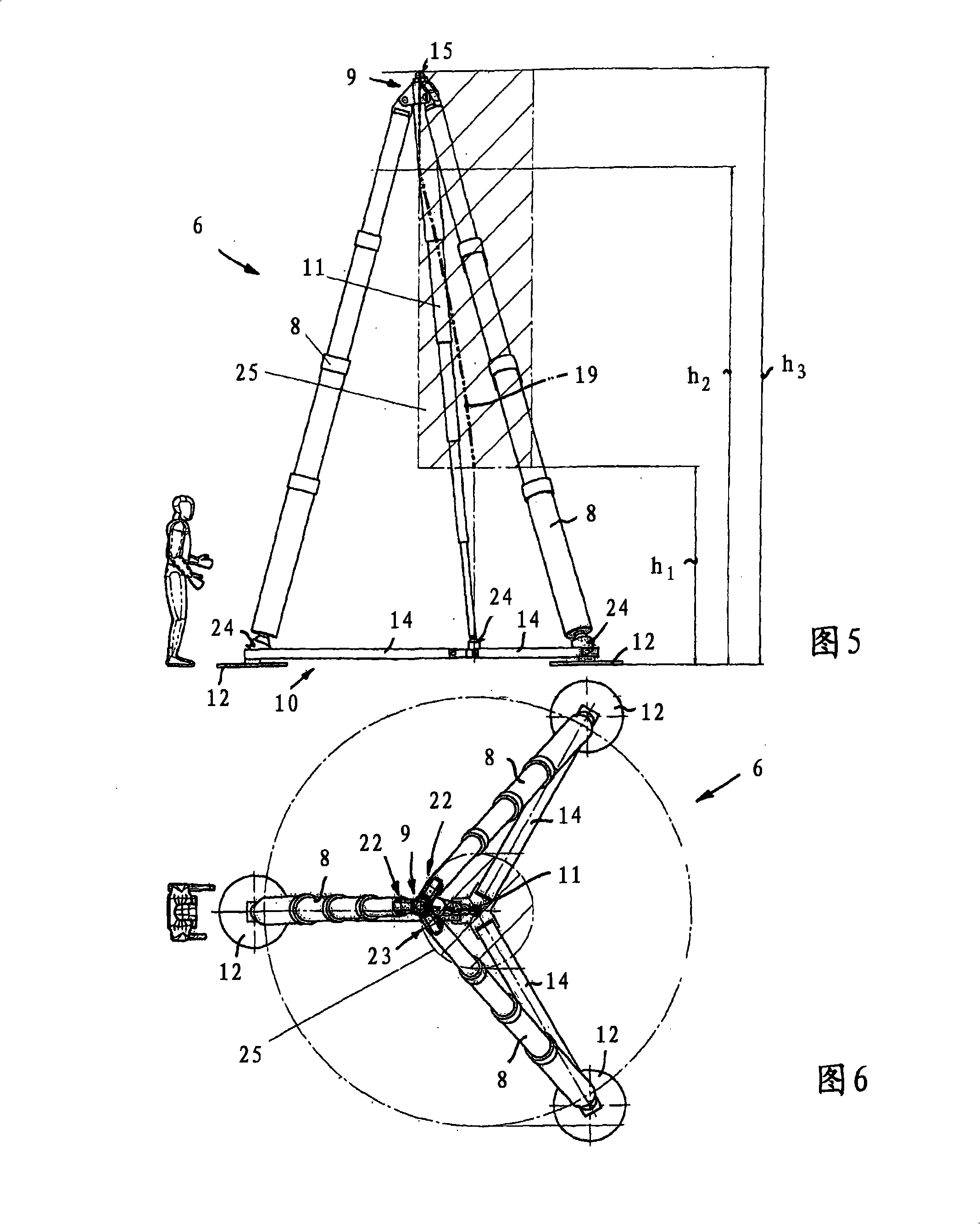
[0040] In the exemplary embodiment, the tripod lift 6 has a triple telescopic lifting cylinder 8, which is arranged in the shape of a triangular cone, and whose upper end acts on a pair of contact points 9, and is supported on the ...


PUM


Abstract

A lifting system (1) is used for lifting loads, for example for lifting and recovering an aircraft (2) following an accident, and has a lift (6) which can be positioned underneath a load, in particular underneath a mainplane (5) of an aircraft. The lift (6) has at least three lifting cylinders (8) or similar lifting elements and a docking head (9) for coupling to a load holding point. A measurement system is provided in order to detect the position of the docking head (9) and to measure the load vector that occurs at the docking head (9). A control device is connected to the measurement system, for mutually independent, load-controlled or movement-controlled confirmation of the individual lifting cylinder drives.

Description

technical field [0001] The invention relates to a lifting system for lifting a load, comprising a hoist capable of being positioned beneath the load. Background technique [0002] The load to be lifted may be an aircraft, in particular a wrecked aircraft to be rescued. An aircraft that crashes during takeoff or landing, for example an aircraft that skids off a runway, may have damage to the landing gear, one or more of which may snap off or fall off, leaving the aircraft lying on the ground with one wing tilted. [0003] To rescue the aircraft, the aircraft had to be lifted on the sunken side to gain access to the damaged undercarriage and thus put the aircraft in a transportable condition. [0004] In this case, a damaged undercarriage can be repaired in the raised position, or an attempt can be made to lower a non-extended undercarriage. [0005] Regardless of the various damages, it is necessary to raise the aircraft and bring it into a position where it can slide or be...

Claims


Application Information

Patent Timeline
IPC IPC(8): B66F3/46B66F7/20B64F5/00
CPCB66F3/46B66F7/20B64F5/0036B64F5/50
Inventor L·米科夫斯基K·米勒
Owner 海德罗器械(升降机)有限及两合公司
Why Eureka
Try Eureka