Manifold drawing technique and special-purpose equipment thereof

A technology of drawing process and special equipment, which is applied in the field of manifold drawing process and its special equipment, can solve the problems of large local stress and difficult inspection of fillet welds, and achieve energy saving, appropriate temperature range, and not easily oxidized skin Effect

Active Publication Date: 2010-12-08
NINGBO LIANTONG EQUIP MFG
View PDF1 Cites 0 Cited by
  • Summary
  • Abstract
  • Description
  • Claims
  • Application Information

AI Technical Summary

Problems solved by technology

However, there is no heating process in the forming process, and there is a large local stress at the fillet weld, which is not easy to inspect, and welds appear to form product defects

Method used


Image

  • Manifold drawing technique and special-purpose equipment thereof
  • Manifold drawing technique and special-purpose equipment thereof
  • Manifold drawing technique and special-purpose equipment thereof

Examples


Embodiment

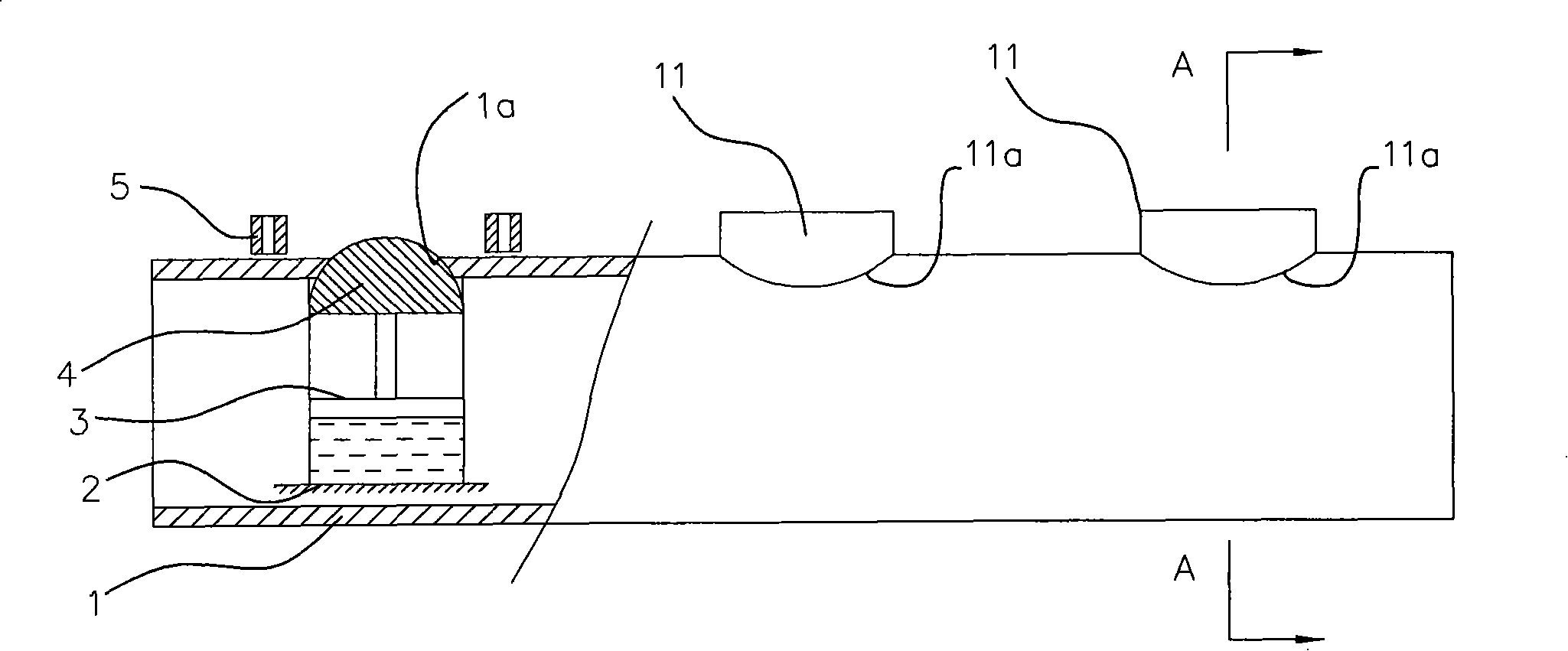
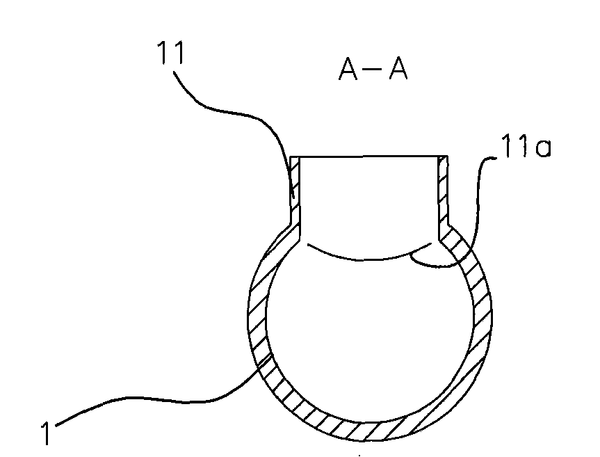
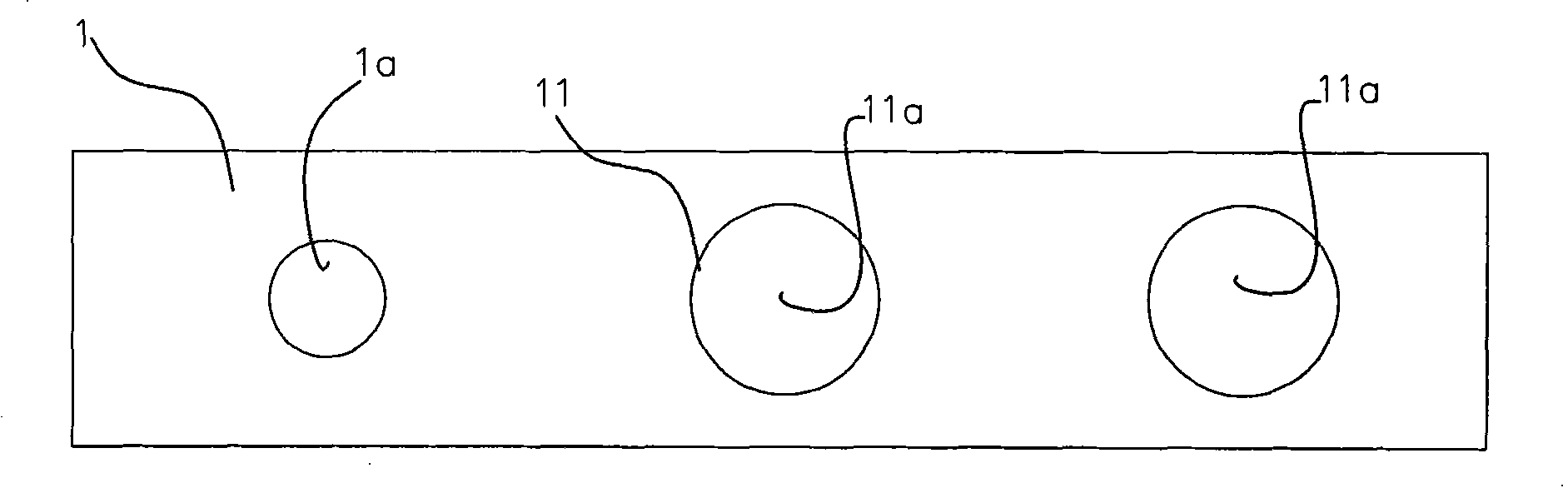
[0027] Example: refer to Figure 1 to Figure 4 , a manifold drawing process, including a material selection step: selecting a formed tube blank as the main pipe 1, which also includes the following steps:

[0028] Opening step: at least one through hole 1a is opened on the side wall of the main pipe 1; fixing step: fix the main pipe 1;

[0029] Steps for placing the drafting mold: Put a drafting mold 4 in the main pipe 1, and the drafting mold 4 is matched with the drawing machine; the drafting mold 4 is preferably a self-made irregular drafting shape. The pulling resistance is small and the pulling is uniform.

[0030] Positioning step: positioning the draft 4 on the inner hole wall of the through hole 1a;

[0031] Heating step: use the induction heater 5 to heat the through hole 1a of the main pipe 1 as the peripheral part of the body of the branch pipe 11, and the heating temperature is controlled by a thermometer, and the range is from 750°C to 1300°C;

[0032] Drawing ...


PUM


Abstract

The invention discloses a manifold drawing technology and a special device thereof. The manifold drawing technology of the invention includes the step of cutting a hole: a through hole is cut at the side wall of a main pipe; the step of fixing: the main pipe is fixed; the step of placing a drawing mould: the drawing mould matched with a drawing machine is placed in the main pipe; the step of positioning: the drawing mould is positioned at the inner hole wall of the through hole; the step of heating: an induction heater is controlled by a temperature tester to heat the main pipe; the step of drawing and shaping: the drawing machine is lifted by hydraulic pressure so as to cause the plastic deformation around the through hole and pull out a branch pipe. The special device of the manifold drawing technology has the structure that the end of a rod body with a hydraulic cylinder is connected with a drawing mould the top end of which can be matched and positioned on the inner hole wall of the through hole of the main pipe; the body part at the periphery of the through hole of the main pipe is assembled with the induction heater controlled by temperature control equipment. The manifold drawing technology and the special device of the invention have the advantages of reasonable structure, uniform heating, good drawing effect, energy saving and high strength of products and are not likely to produce oxide scale.

Description

Technical field [0001] The invention relates to the technical field of pipeline processing in industries such as petroleum, chemical industry, electric power and environmental protection, and in particular relates to a collection pipe drawing process and its special equipment. Background technique [0002] At present, the connection between the collecting pipe and the heating pipe mostly adopts an integral welding structure. The fillet weld of the welded pipe interface has great local stress and is difficult to inspect. For example, in double-row drawn pipes, the weld can easily form defects and expand to cause Breaks and leaks. The existing technology, such as "Hydraulic Forming Device and Forming Method of Stainless Steel Lined Composite Pipe" with publication number CN1651163A, discloses a stainless steel lined composite pipe forming device. Utilizing the principle of self-tightening sealing, that is, the higher the molding hydraulic pressure, the better the self-tighten...

Claims


Application Information

Patent Timeline
Patent Type & Authority Patents(China)
IPC IPC(8): B21C1/22B21C9/00B21C3/10B21C51/00
Inventor 卢军蔡丽萍连式雄
Owner NINGBO LIANTONG EQUIP MFG
Why Eureka
Try Eureka