Permanent electromagnetic lock

An electromagnetic lock and permanent magnet technology, which is applied in the field of permanent electromagnetic locks, can solve problems such as the energy consumption of permanent electromagnetic locks that cannot be locked, and the suction surface of the suction parts cannot be fully contacted, so as to improve the full contact suction and reliability. Effects of safety and power consumption reduction

Inactive Publication Date: 2008-11-26
大连泰戟尔科技有限公司
View PDF0 Cites 7 Cited by
  • Summary
  • Abstract
  • Description
  • Claims
  • Application Information

AI Technical Summary

Problems solved by technology

[0003] The present invention is to solve the technical problem that the lock cannot be locked without electricity and the problem that the energy consumption of the existing permanent electromagnetic lock is relatively large, and further solves the problem that the suction surface between the suction parts cannot be fully contacted, and provides a locked state that does not consume Electric energy, the use of energy consumption is relatively small, the permanent electromagnetic lock that is easy to control and use, and further provides a permanent electromagnetic lock that can fully contact the suction surface between the suction parts

Method used


Image

  • Permanent electromagnetic lock
  • Permanent electromagnetic lock
  • Permanent electromagnetic lock

Examples


specific Embodiment

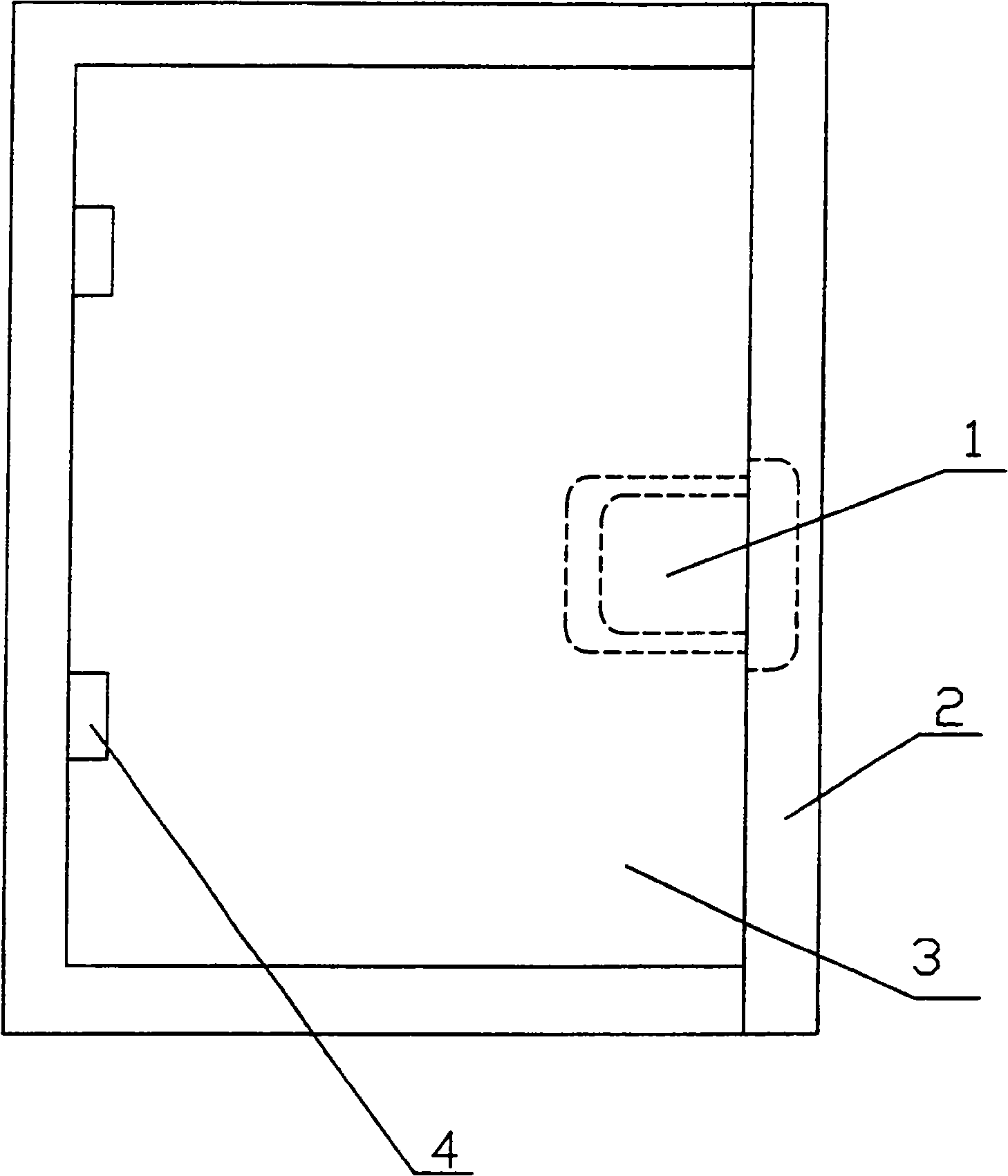
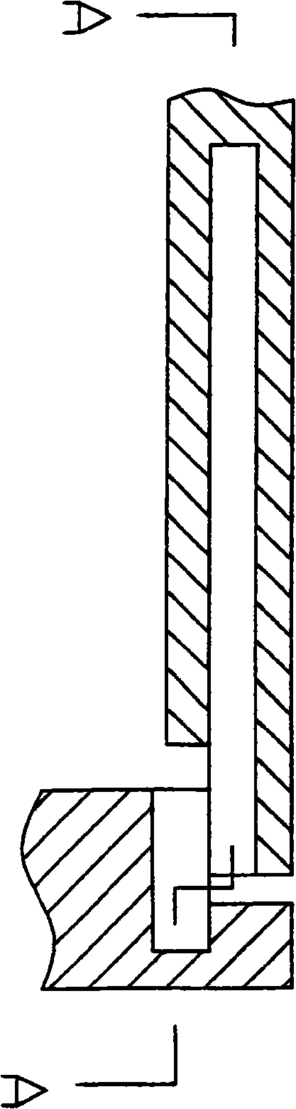
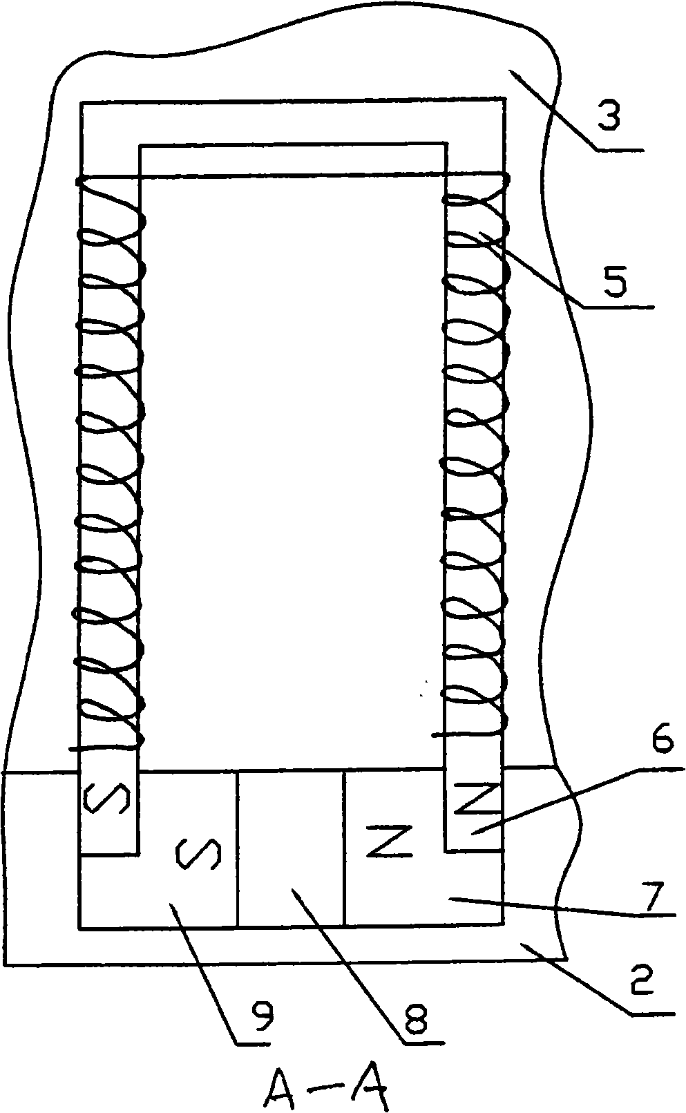
[0007] Specific embodiment: this anti-theft door permanent electromagnetic lock 1 of the present invention is contained in door frame 2 and cooperates bottle with door frame by the hinged door leaf 4 of hinge 4, and just door frame and door leaf are provided with permanent magnet and electromagnet respectively. Door frame 2 is fixed with permanent magnet 8 with the relative position of door leaf limit, and permanent magnet one end magnetic pole is connected with a steel plate as iron extension block 9 or two electromagnet two ends magnetic poles are respectively connected with a steel plate as iron extension block 7,9. The iron extension blocks 7, 9 are connected with the door frame 2 by screws, and the connection holes of the screws and the iron extension blocks are in a loose contact state, which can further increase the sufficient suction contact between the suction parts; the permanent magnet and its magnetic poles are connected with iron A rubber pad is clamped between the...


PUM


Abstract

A permanent electromagnetic lock is provided with a frame and a fan matched with the frame; the frame and the fan are respectively provided with a permanent magnet and an electric magnet. The iron core end part of the electric magnet is corresponding to the pole of the permanent magnet. The frame and the fan are locked by utilizing the suction of the permanent magnet to the electric magnet without using electricity. The electric magnet is briefly electrified; the direction of the magnetic field of the electric magnet is opposite to the direction of the magnetic field of the permanent magnet to generate a repulsive force and release the closing state of a magnetic lock. The pole end of the permanent magnet is better to be connected with an iron extending block; the iron core end part of the electric magnet is correspondingly sucked with the iron extending block at the pole end of the permanent magnet. The permanent magnet or the pole end thereof is connected with the iron extending block which is loosely connected with the frame or the fan or the permanent magnet or the pole end thereof is connected with the iron extending block; a soft cushion or an elastic cushion is clamped between the permanent magnet and the frame or the fan or between the pole end and the frame or the fan so as to ensure the suction pieces to be fully contacted and enhance the suction force.

Description

Technical field: [0001] The permanent electromagnetic lock is arranged between the frame and the fan, and the frame and fan are closed by permanent magnetic force, and the lock is opened by the electromagnetic magnetic force opposite to the direction of the permanent magnetic field. Background technique: [0002] The existing permanent electromagnetic lock has a frame and a fan matched with the frame, and the frame and the fan are respectively provided with an armature and an electromagnet. When the electromagnet is energized, a magnetic force is generated to attract the armature and lock the frame and the fan. When the electromagnet is powered off and loses its magnetic force, it will not attract the armature, and the locked state will be released, and the fan can be opened. However, this kind of permanent electromagnetic lock has to be energized all the time in the locked state of the frame and the fan, and the energy consumption is relatively large, and once the power is...

Claims


Application Information

Patent Timeline
Patent Type & Authority Applications(China)
IPC IPC(8): E05B47/02
Inventor 秦子建
Owner 大连泰戟尔科技有限公司
Why Eureka
Try Eureka