Display device
A technology of liquid crystal display device and liquid crystal display panel, which is applied in the direction of coupling device, optics, instrument, etc., can solve the problem of fluorescent tube installation working hours, discharge and other problems, and achieve excellent pressure resistance characteristics, ensure reliability and remarkable effect Effect
- Summary
- Abstract
- Description
- Claims
- Application Information
AI Technical Summary
Problems solved by technology
Method used
Image

Examples
Embodiment 1
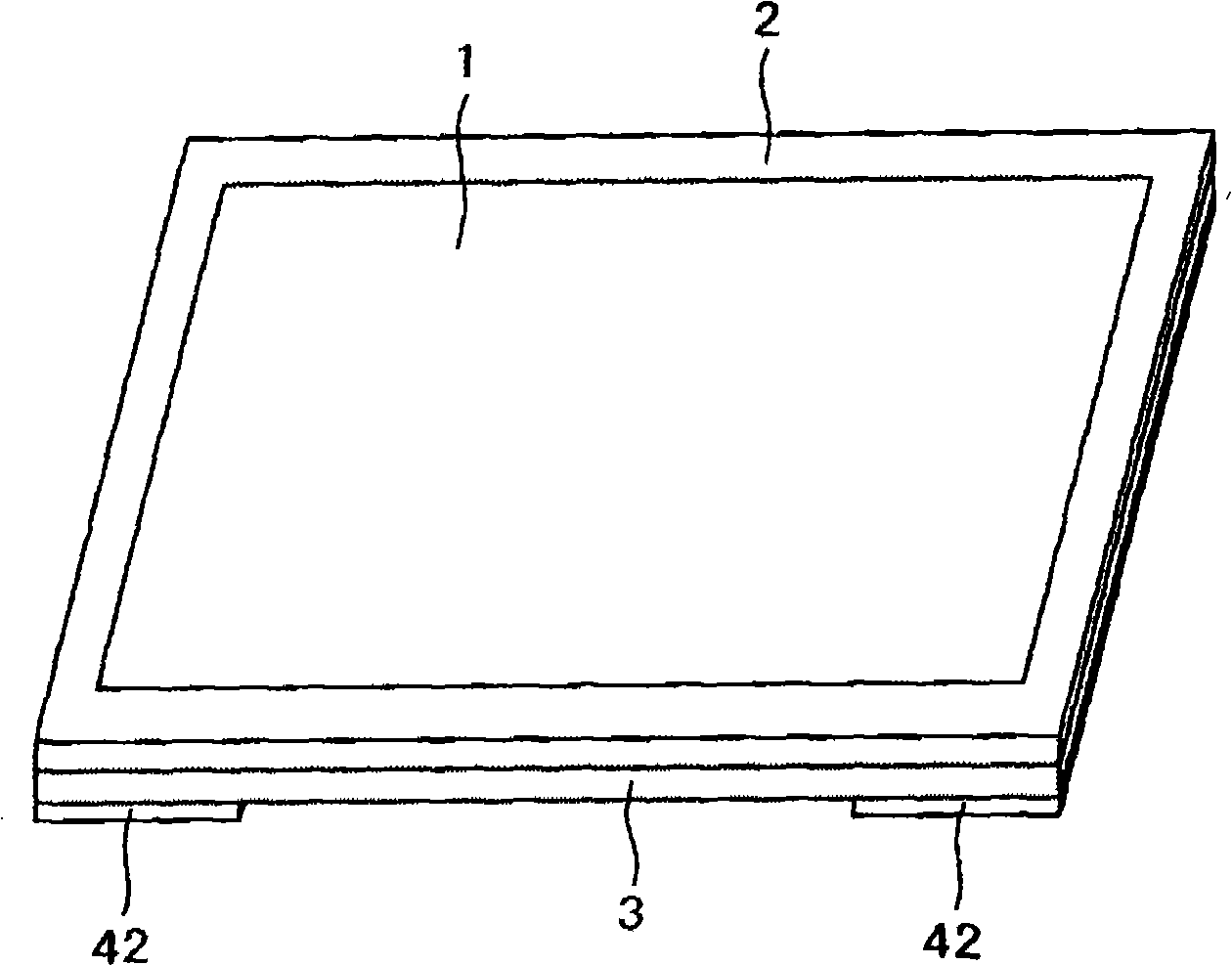
[0075] figure 1 It is a schematic diagram of a liquid crystal display device. A liquid crystal display panel 1 is housed in a frame-shaped front frame 2 . The liquid crystal display panel 1 is composed of a TFT substrate formed with image signal lines, scanning lines, pixel electrodes, and thin film transistors (TFTs), an opposite substrate formed with a color filter substrate, etc., a lower polarizing plate attached to the TFT substrate, It is composed of an upper polarizing plate pasted on the opposite substrate. The liquid crystal display panel 1 is covered by the front frame 2, in figure 1 Only the display screen of the liquid crystal display panel 1 can be seen.
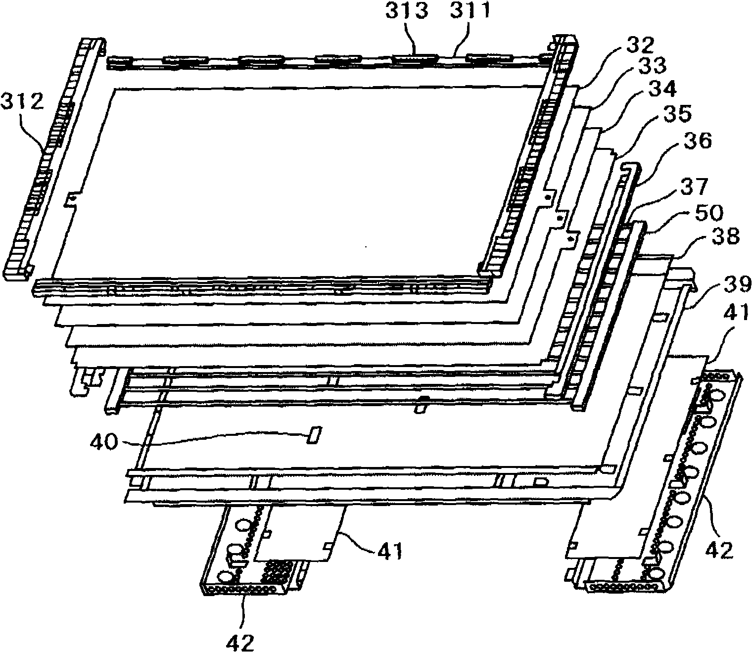
[0076] A backlight 3 is provided on the back of the liquid crystal display panel 1 . An image is formed by using the liquid crystal display panel 1 to turn light from the backlight 3 on and off for each pixel. In order to efficiently emit light to the liquid crystal display panel 1, the backlight 3 is compo...
Embodiment 2
[0106] Figure 25 is the connector 50 of the second embodiment of the present invention. exist Figure 25 In this case, a cutout 61 is formed between the insertion hole 51 of the fluorescent tube 37 and the insertion hole 51 instead of the recess 60 . That is, the connector 50 of the present embodiment has a structure in which a connecting portion 50 for one fluorescent tube is connected through the bottom and the back portion. According to the structure of the present embodiment, compared with the first embodiment, the strength of the inner side wall 57 between the insertion hole 51 and the insertion hole 51 can be further weakened. Therefore, the fluorescent tube 37 can be inserted more easily, and the stress on the fluorescent tube 37 and the cable at the time of insertion can be made smaller.
[0107] On the other hand, since the inner side wall 57 exists between the insertion hole 51 of the fluorescent tube 37 of the connector 50 and the insertion hole 51, the creeping...
PUM
| Property | Measurement | Unit |
|---|---|---|
| thickness | aaaaa | aaaaa |
| thickness | aaaaa | aaaaa |
| length | aaaaa | aaaaa |
Abstract
Description
Claims
Application Information
 - R&D
- Intellectual Property
- Life Sciences
- Materials
- Tech Scout
- Unparalleled Data Quality
- Higher Quality Content
- 60% Fewer Hallucinations
Browse by: Latest US Patents, China's latest patents, Technical Efficacy Thesaurus, Application Domain, Technology Topic, Popular Technical Reports.
© 2025 PatSnap. All rights reserved.Legal|Privacy policy|Modern Slavery Act Transparency Statement|Sitemap|About US| Contact US: help@patsnap.com