Wire structure and backlight module group applying same

A backlight module and wire technology, applied in nonlinear optics, conductors, optics, etc., can solve problems such as limiting high-voltage wires, low-voltage wires 120 breakage, and lamp failure to operate, so as to achieve the effect of improving reliability

Inactive Publication Date: 2008-11-26
CHUNGHWA PICTURE TUBES LTD
View PDF0 Cites 2 Cited by
  • Summary
  • Abstract
  • Description
  • Claims
  • Application Information

AI Technical Summary

Problems solved by technology

[0006] The heat-shrinkable sleeve 130 tightly binds the high-voltage wire 110 and the low-voltage wire 120, thereby restricting the movement of the high-voltage wire 110 and the low-voltage wire 120
However, when performing assembly work or lighting test of the backlight module, please refer to figure 2 , workers often pull or bend the wire structure 100, and the internal high-voltage wires 110 and low-voltage wires 120 are also squeezed and pulled
At this time, if the pulled part is the thinner low-voltage wire 120, it is easy to cause the breakage of the low-voltage wire 120, and make the entire lamp tube unable to operate.

Method used


Image

  • Wire structure and backlight module group applying same
  • Wire structure and backlight module group applying same
  • Wire structure and backlight module group applying same

Examples


Embodiment Construction

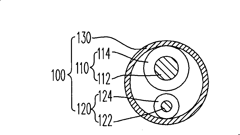
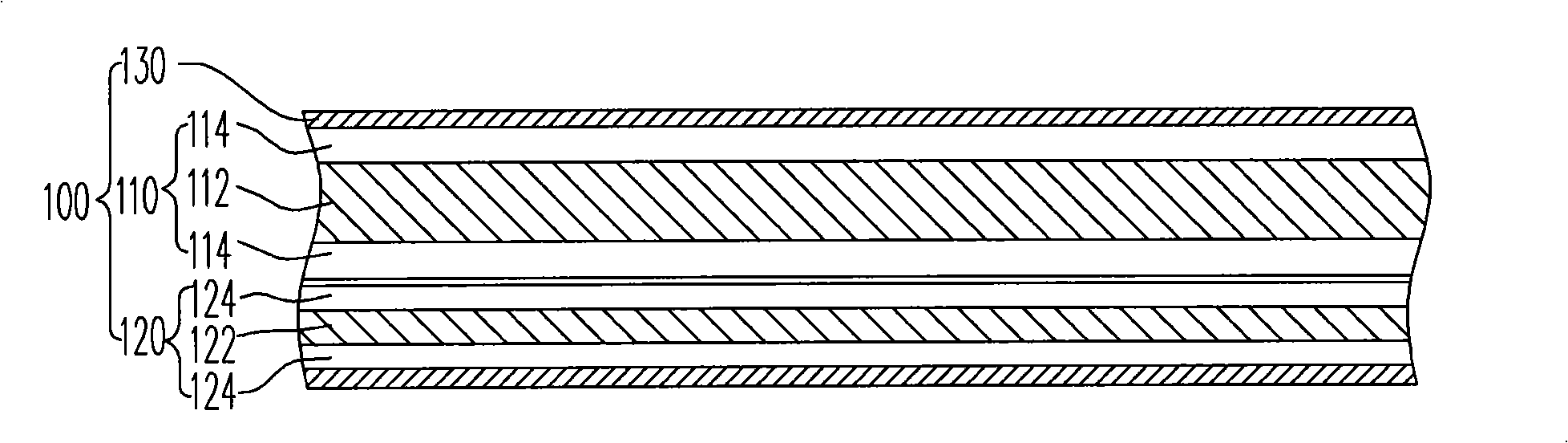
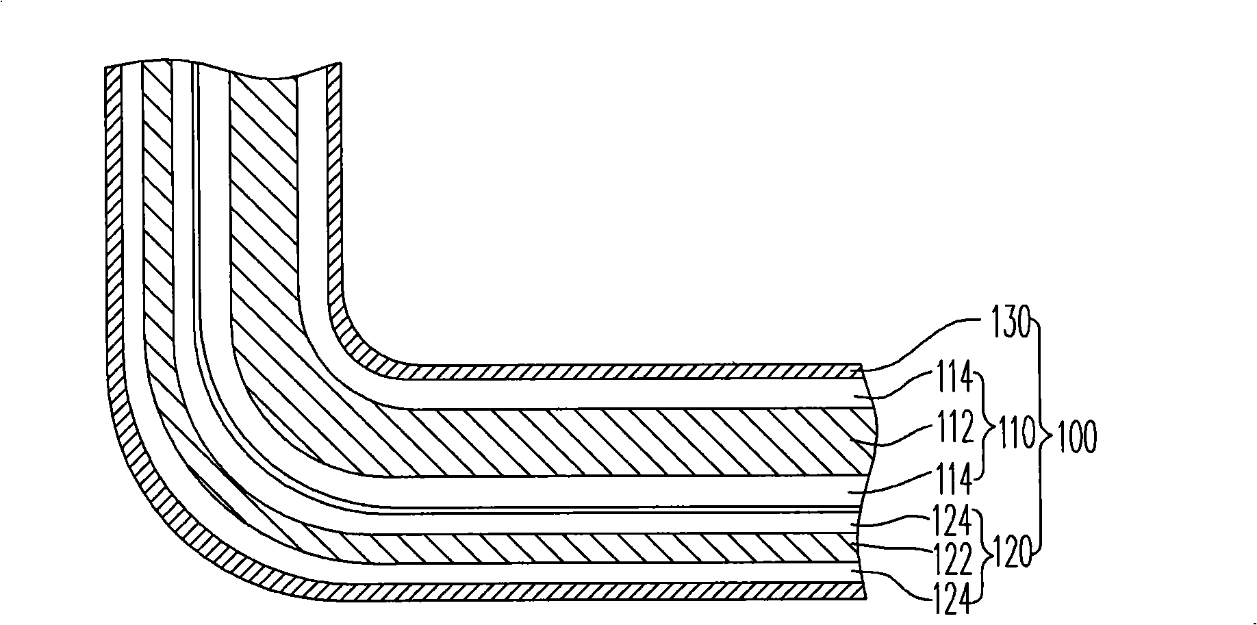
[0023] Figure 3A Shown is a transverse cross-sectional view of a wire structure according to a preferred embodiment of the present invention; Figure 3B shown along the Figure 3A The longitudinal cross-sectional view of the wire structure drawn by the I-I' section line. Please also refer to Figure 3A and 3B , the wire structure 200 mainly includes a high voltage wire 210 , a low voltage wire 220 and a heat shrinkable sleeve 230 .

[0024] The high-voltage wire 210 is composed of a thicker metal wire 212 and an insulating layer 214 covering its periphery to provide high-voltage current. The low-voltage wire 220 is composed of a thinner metal wire 222 and an insulating layer 224 surrounding it to provide low-voltage current. The heat-shrinkable sleeve 230 is wrapped around the high-voltage wire 210 and the low-voltage wire 220 for protection and insulation.

[0025] The feature of the present invention is that a plurality of perforations 232 are formed on the surface of...


PUM


Abstract

The invention discloses a conductor structure, comprising a high-voltage conductor, a low-voltage conductor and a heat-shrinkable tubing. The heat-shrinkable tubing is coated around the peripheries of the high-voltage conductor and the low-voltage conductor, and the surface of the tubing is provided with a plurality of broken holes for partially exposing the high-voltage conductor and the low-voltage conductor. A contact area among the heat-shrinkable tubing, the high-voltage conductor and the high-voltage conductor can be reduced by aid of the designed broken holes on the heat-shrinkable tubing, and thereby the problem that the conductor structure in the prior art is easy to result in breaking when the conductor structure is pulled can be avoided.

Description

technical field [0001] The present invention relates to a wire structure, and in particular to a pull-resistant wire structure and a backlight module using the wire structure. Background technique [0002] Liquid crystal display (Liquid Crystal Display, LCD) has been widely used recently. With the improvement of drive technology, it has the advantages of low power consumption, thin and light weight, and low voltage drive. It has been widely used in video recording and playback Video machines, notebook computers, desktop monitors and various projection equipment. [0003] Generally, the more common liquid crystal display is thin film transistor liquid crystal display (TFT-LCD). Since the thin film transistor liquid crystal display itself does not emit light, it needs to use the white surface light source of the backlight module to achieve the effect of imaging. Generally, there are two types of light sources used in thin film transistor liquid crystal displays: cold cathode ...

Claims


Application Information

Patent Timeline
Patent Type & Authority Applications(China)
IPC IPC(8): H01B7/00H01B7/18G02F1/1335
Inventor 张庆龙
Owner CHUNGHWA PICTURE TUBES LTD
Why Eureka
Try Eureka