Robot simulation apparatus

A simulation device and robot technology, applied in the direction of conveyor control devices, instruments, manipulators, etc., can solve problems such as excessive time and difficulty in building a robot production system

Inactive Publication Date: 2008-12-03
FANUC LTD
View PDF3 Cites 32 Cited by
  • Summary
  • Abstract
  • Description
  • Claims
  • Application Information

AI Technical Summary

Problems solved by technology

Therefore, when adjusting the supply interval, the supply speed, the shape of the target object, etc., professional knowledge and trial and error are required, and a lot of time is required for adjustment, etc., and there is a problem that it is difficult to construct a robot production system.

Method used


Image

  • Robot simulation apparatus
  • Robot simulation apparatus
  • Robot simulation apparatus

Examples


Embodiment Construction

[0031] Hereinafter, a robot simulation device (hereinafter referred to as "simulation device") related to the present invention will be described based on the drawings. In addition, the same code|symbol is attached|subjected to the common part in each figure, and repeated description is abbreviate|omitted.

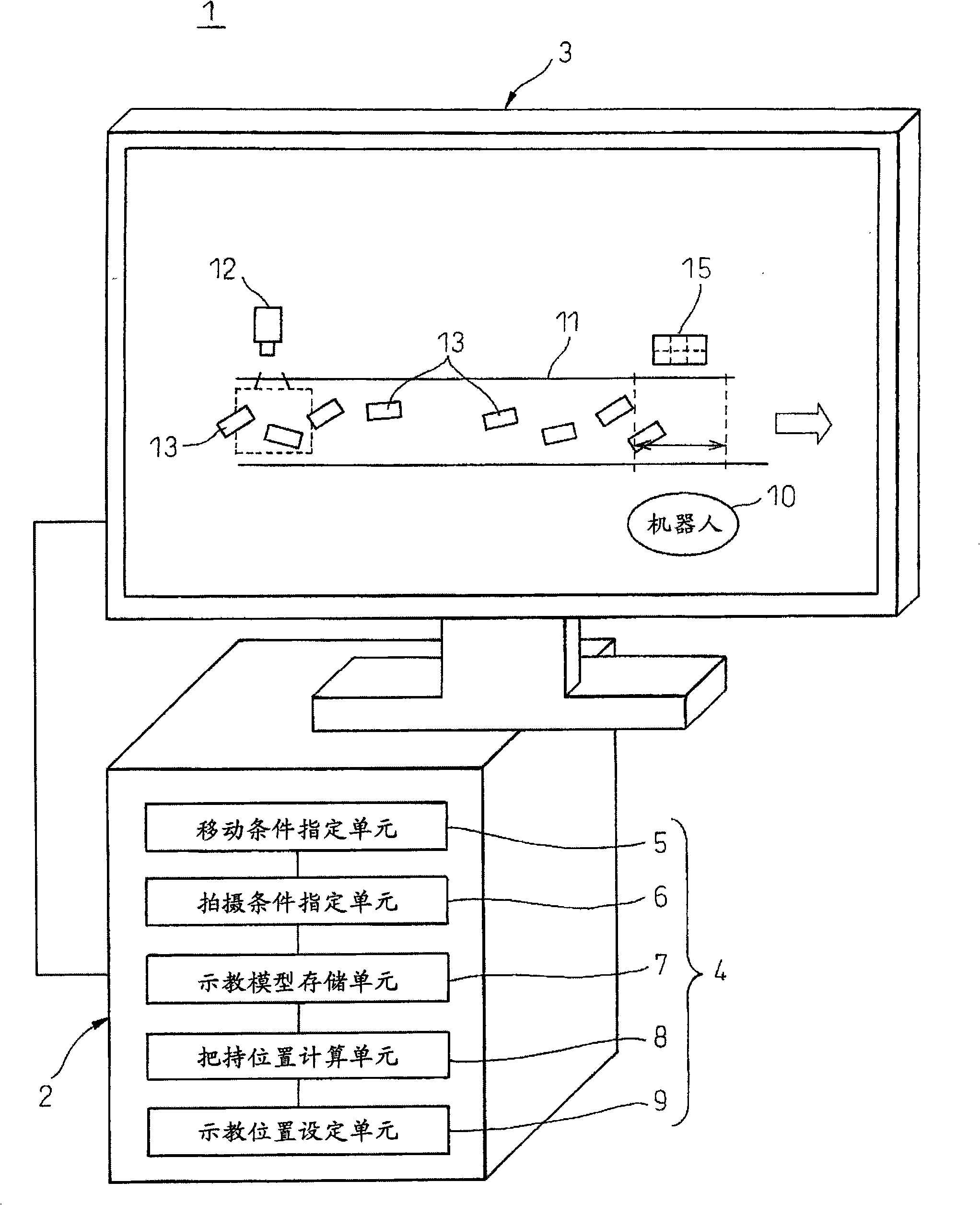
[0032] The simulation device 1 of this embodiment performs image processing on image data captured by a camera, and can simulate the tracking operation of an actual robot that tracks an object conveyed by a conveyor belt (conveying device) and grasps the object at a predetermined position in an off-line state. The picking action of the actual robot, such as figure 1 As shown, it has a device main body 2 with a control function and a display 3 ( figure 1 ). The display (display unit) 3 uses a liquid crystal display, a CRT, or the like, and graphically displays model data and the like of the robot 10 having a manipulator on a screen. Also, while in figure 1 Although not ...


PUM


Abstract

A robot simulation apparatus including: a display section which displays models of at least a conveyance apparatus, an object, and a robot respectively laid out at predetermined positions; a movement condition designating section which designates a direction and a speed of movement of the object; a imaging condition designating section which designates a relative position of the camera with respect to the object and imaging condition in order to obtain a still image of the object located within an imaging area; a teaching model storage section which stores a teaching model of the object to be compared with the still image obtained with the camera; ; a grasping position calculating section which calculates a grasping position of the object to be grasped by the robot based on a position and an attitude of the object obtained by comparing the still image with the teaching model, and on the direction and the speed of movement of the object; and a teaching position setting section which sets a teaching position for said robot based on the grasping position.

Description

technical field [0001] The present invention relates to a robot simulator for simulating, in an off-line state, the motion of a robot that grips an object while tracking the object conveyed by a conveyance device. Background technique [0002] As an example of a robot production method for tracking an object being conveyed and holding the object, a visual tracking method disclosed in Japanese Patent No. 3002097 is known. The so-called visual tracking method refers to the use of visual sensors to measure the position and posture of the moving object conveyed on the conveyor belt as the conveying device, and to track the object based on the measured position and posture of the object, and to correct the grasping position at the same time. The method of teaching the position of the robot and holding the object. Patent Document 1 discloses a technology in which a robot performs an operation accompanied by tracking an object in order to execute a robot operation on an object mov...

Claims


Application Information

Patent Timeline
Patent Type & Authority Applications(China)
IPC IPC(8): B25J9/22B25J13/08B25J19/00B25J19/04B65G43/08
CPCB25J9/1671G05B2219/39484G05B2219/40308G05B2219/39543B25J9/1669Y02P90/02
Inventor 长塚嘉治近江达也
Owner FANUC LTD
Why Eureka
Try Eureka