

Pneumatic tire
A technology for pneumatic tires and treads, applied in tire parts, tire treads/tread patterns, transportation and packaging, etc., can solve problems such as uneven ground pressure and insufficient braking performance on ice surfaces, etc. Achieve uniform ground pressure, improve ice braking performance, and easily absorb deformation.
- Summary
- Abstract
- Description
- Claims
- Application Information
AI Technical Summary
Problems solved by technology
Method used
Image

Examples
no. 1 approach
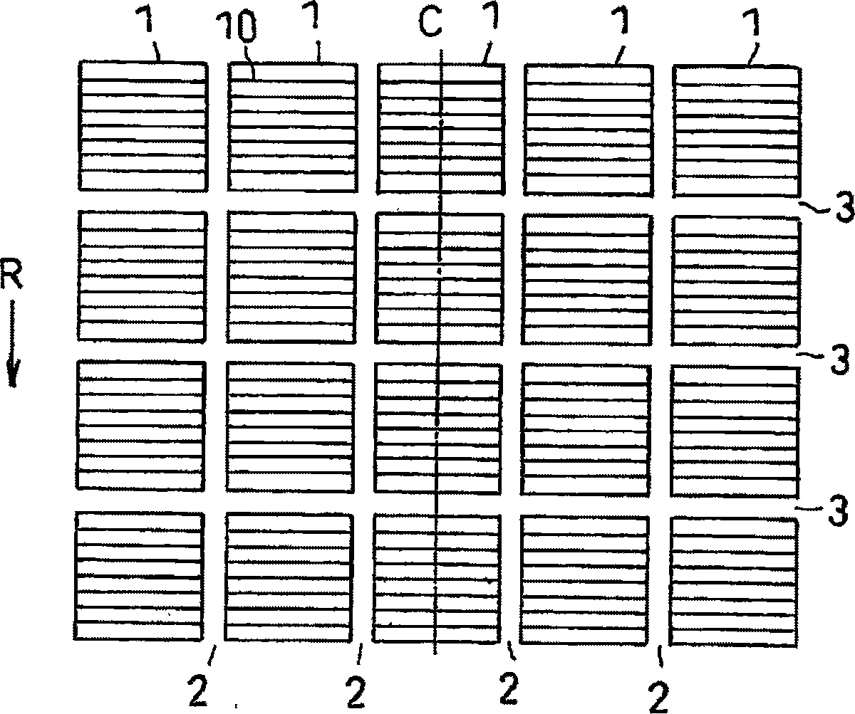
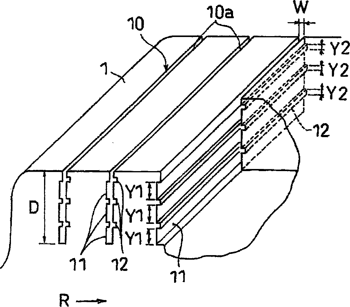
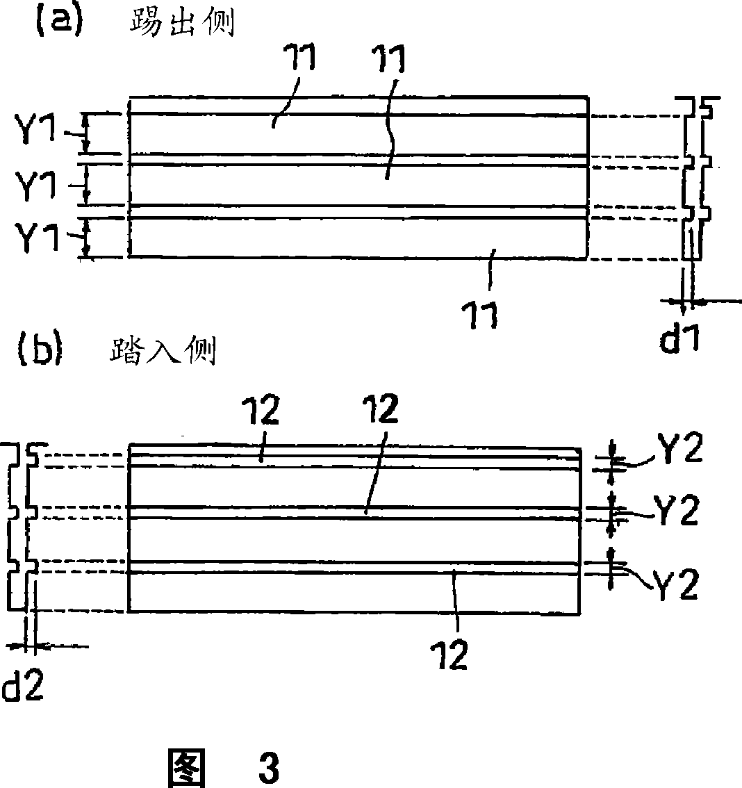
[0027] figure 1 is a development plan view showing the tread of the pneumatic tire according to the first embodiment of the present invention. figure 2 A perspective view showing the main part of the block provided in the tread is shown in a partially broken way. image 3 It is a front view which shows the inner wall surface of the sipe formed in this block.
[0028] like figure 1 As shown, the pneumatic tire according to the present embodiment is provided with a tread pattern having a plurality of blocks 1 (an example of land portions) in which sipes 10 are shaped to extend linearly in the tire width direction. Each block 1 is partitioned by main grooves 2 extending in the tire circumferential direction and lug grooves 3 extending in the tire width direction, and 5 rows of blocks 1 are arranged symmetrically with respect to the tire equator C. In this case, the arrow R indicates the direction of rotation of the tire.
[0029] like figure 2 and 3 As shown, a pluralit...
no. 2 approach
[0043] Since the second embodiment has the same structure and effect as the first embodiment except for the following structure of the sipe, the differences will be mainly described and the common points will be omitted. In this case, the same reference numerals will be associated with the same components and positions as those already described, and repeated descriptions will be omitted.
[0044] Figure 4 is a perspective view showing, partially broken away, the main portion of a block provided in the tread of a pneumatic tire according to a second embodiment of the present invention. Figure 5 It is a front view which shows the inner wall surface of the sipe formed in this block. In the present embodiment, the wide portions 21 and 22 extending in the sipe length direction are formed on the kick-out side and the step-in side of the sipe 20, respectively, and the wide portions 21 and 22 are formed at the sipe depth Creates an undulating zigzag in the direction.
[0045] Th...
no. 3 approach
[0048] Since the third embodiment has the same structure and effect as the first embodiment except for the following structure of the sipe, the differences will be mainly described and the common points will be omitted. In this case, the same reference numerals will be associated with the same components and positions as those already described, and repeated descriptions will be omitted.
[0049] Image 6 is a perspective view showing the main part of the block according to the third embodiment of the present invention in a partially broken way. Figure 7 It is a front view which shows the inner wall surface of the sipe formed in this block. In the present embodiment, the wide portions 31 and 32 extending in the sipe length direction are formed on the kick-out side and the step-in side of the sipe 30, respectively, and the kick-out side wide portion 31 is formed at the sipe depth In a zigzag shape undulating in the direction, the step-in side wide portion 32 is formed in a s...
PUM
 Abstract
Description
Claims
Application Information