Transmitting apparatus, receiving apparatus, radio communication system and method

A technology for a receiving device and a transmitting device, which is applied in baseband systems, transmission systems, digital transmission systems, etc., can solve problems such as reducing reception performance

Inactive Publication Date: 2008-12-03
NEC CORP
View PDF1 Cites 11 Cited by
  • Summary
  • Abstract
  • Description
  • Claims
  • Application Information

AI Technical Summary

Problems solved by technology

[0011] Generally in radio communication systems, reception performance is degraded due to multipath interference signals, noise power generated in the receiver, etc.

Method used


Image

  • Transmitting apparatus, receiving apparatus, radio communication system and method
  • Transmitting apparatus, receiving apparatus, radio communication system and method
  • Transmitting apparatus, receiving apparatus, radio communication system and method

Examples


Embodiment Construction

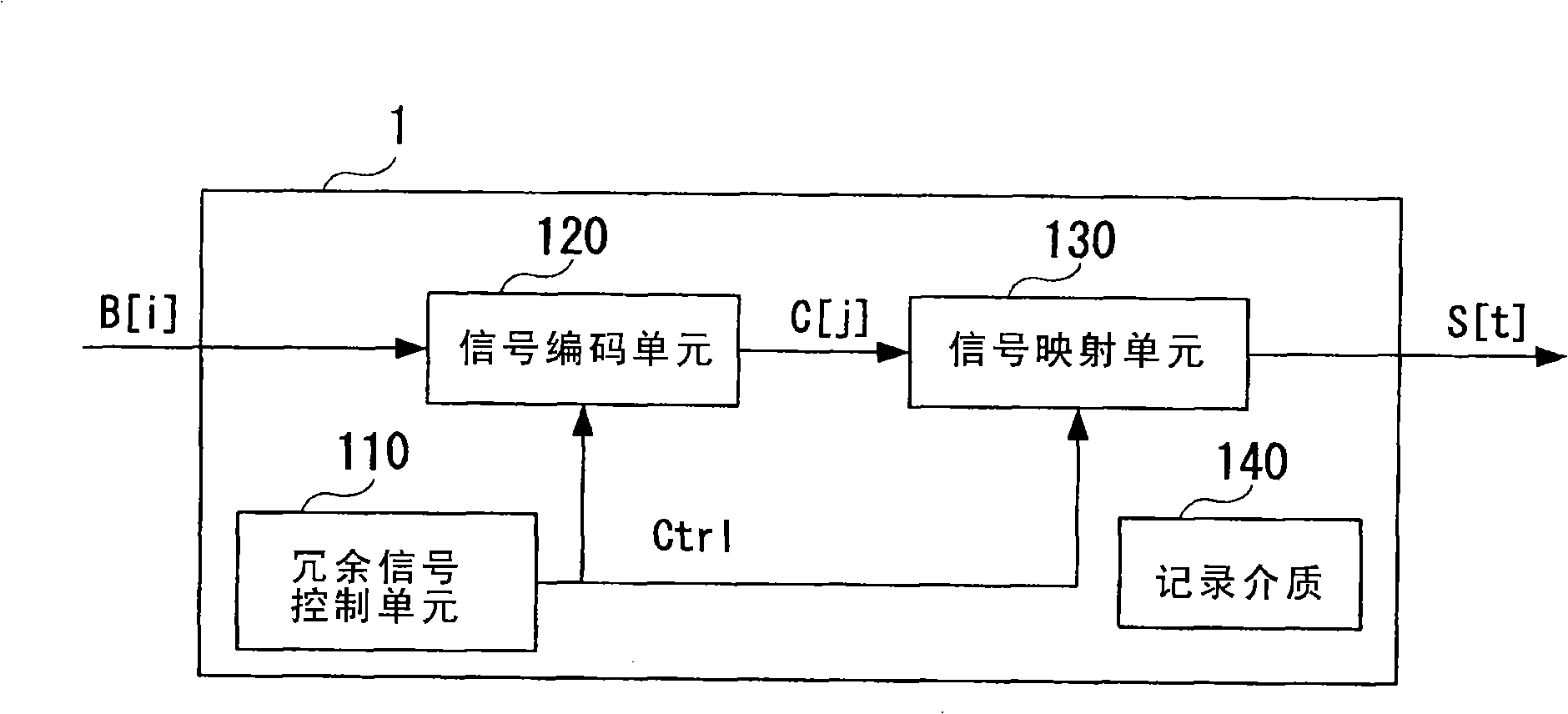
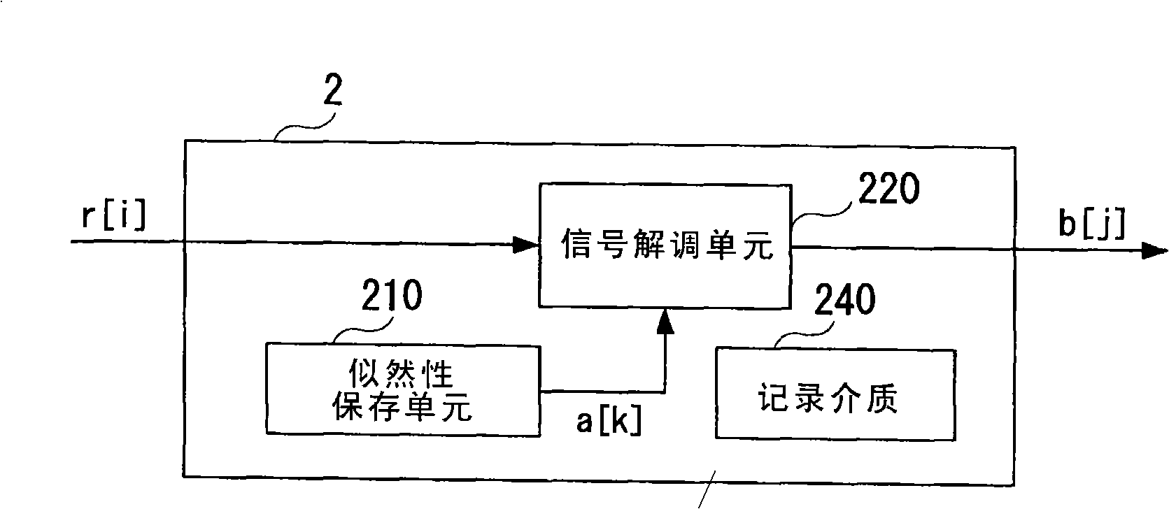
[0042] Exemplary embodiments of the present invention will be described below with reference to the accompanying drawings. The following description is shortened and simplified appropriately for clarity of illustration. In the drawings, elements and equivalents having the same structure and function are denoted by the same reference symbols, and redundant description thereof will be omitted.

[0043] In this description, when there are a plurality of identical elements to be distinguished from each other, the plurality of elements are distinguished by adding "-n" (n≧0) to symbols. For example, in FIG. 13, a plurality of likelihood replacement units 522-0 to 522-2 are shown. In the description with reference to FIG. 13 , the likelihood replacement unit 522 represents one or more likelihood replacement units 522-0 to 522-2, and the likelihood replacement unit 522-n represents a plurality of communication terminal devices distinguished from each other. of each.

[0044] figur...


PUM


Abstract

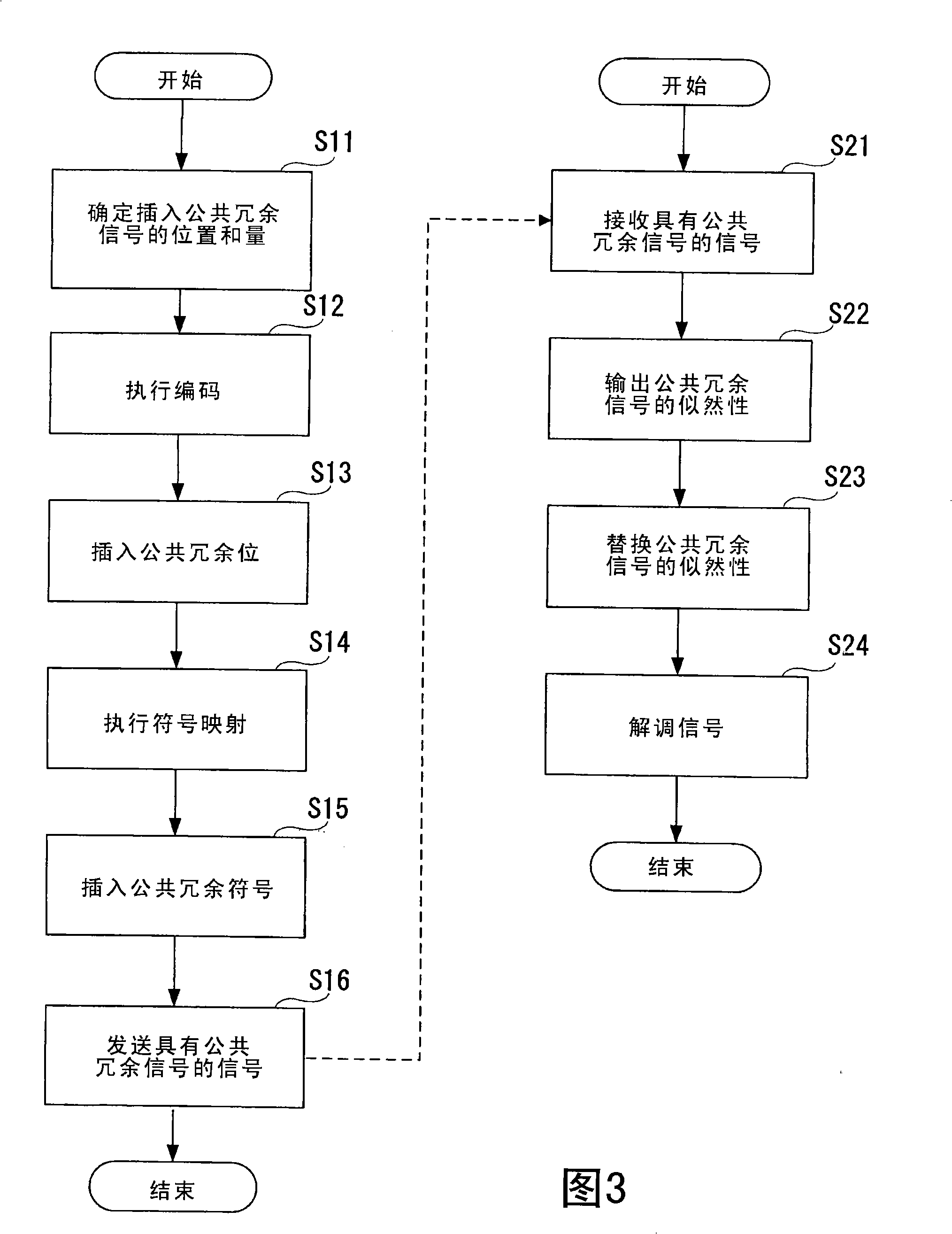
The invention discloses a transmitting device, a receiving device, a radio communication system and a method thereof. At the transmitting terminal, the method stores (determines) control information for appointing an insertion position and an insertion amount for inserting the known redundant signals in the receiving device into an information data sequence, generates an encoded signal sequence through encoding the information data sequence, generates transmitting signal through inserting the redundant signals into the encoded signal sequence based on the stored control information, and transmits the generated transmitting signals. At the receiving end, the method receives the transmitting signals as the receiving signals, stores the likelihood information for the redundant signals included in the receiving signals, computes the likelihood from the receiving signals, replaces the likelihood information for the likelihood of the corresponding redundant signals included in the computed likelihood, and demodulates the signals.

Description

technical field [0001] The present invention relates to a radio communication system, and more particularly to signal transmission and reception techniques. Background technique [0002] In radio communication, research and development are conducted on techniques for controlling radio parameters such as code rates and modulation methods. For example, "Wireless LAN Medium Access Control and Physical Layer Specification: High-speed Physical Layer in the 5GHz Band", IEEE Standard 802.11a, 1999, which is already in practical use. [0003] FIG. 21 is an example of the configuration of a transmission device realizing radio parameter control. [0004] The sending device 21 includes a parameter control unit 2110 , an encoding unit 2120 and a mapping unit 430 . [0005] The parameter control unit 2110 controls the coding rate of the coding unit 2120 through the parameter control signal Ctrl. [0006] Encoding unit 2120 receives information bit string B, encodes information bit str...

Claims


Application Information

Patent Timeline
Patent Type & Authority Applications(China)
IPC IPC(8): H04L1/00
CPCH04L1/0002H04L1/0006H04L1/0045H04L25/0224
Inventor 伊藤匠
Owner NEC CORP
Why Eureka
Try Eureka