Construction structure body, structure unit, and method for the unit

A technology for structural units and structures, which is applied in building components, building structures, buildings, etc., and can solve problems such as the inability to realize the main frame tubular structure.

Inactive Publication Date: 2008-12-03
SEKISUI CHEM CO LTD
View PDF9 Cites 6 Cited by
  • Summary
  • Abstract
  • Description
  • Claims
  • Application Information

AI Technical Summary

Problems solved by technology

Therefore, based on Patent Documents 7 to 8, a tubular structure having a honeycomb-shaped main frame in which structural units are joined to each other cannot be realized

Method used


Image

  • Construction structure body, structure unit, and method for the unit
  • Construction structure body, structure unit, and method for the unit
  • Construction structure body, structure unit, and method for the unit

Examples


Embodiment 1

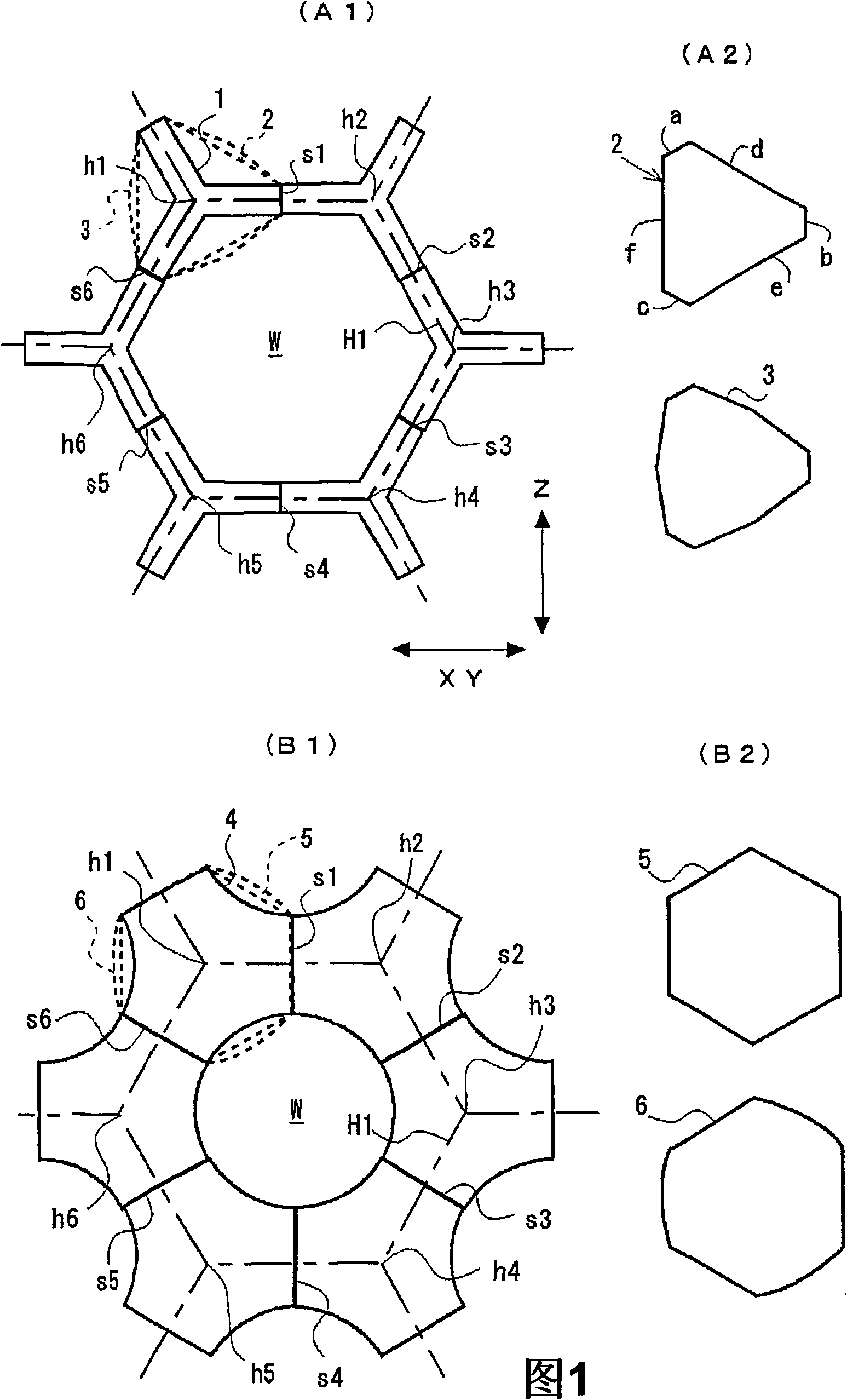
[0163] refer to Figure 7 ~ Figure 14 , an embodiment of a building structure having a main frame arranged in a virtual honeycomb shape and connecting structural units is described.

[0164] Figure 7 (A)-(C) are figures which show an example of the main frame of the building structure constructed using the trident structure unit shown in FIG. (A) is a perspective view of the overall appearance of the tubular frame 100 as the main frame. (B) is enlarged display Figure 7 (A) Front view of a portion of the tubular architecture 100 . (C) is a plan view.

[0165] Figure 7 The tubular structure 100 shown in (A) is constructed based on the virtual honeycomb shape with the hexagonal lattice H1 shown in FIG. . The axis of the pipe extends in the vertical direction. When the trident unit 1 is used as a structural unit arranged on the virtual honeycomb shape, the appearance shape of the completed main frame almost coincides with the basic virtual honeycomb shape. This is beca...

Embodiment 2

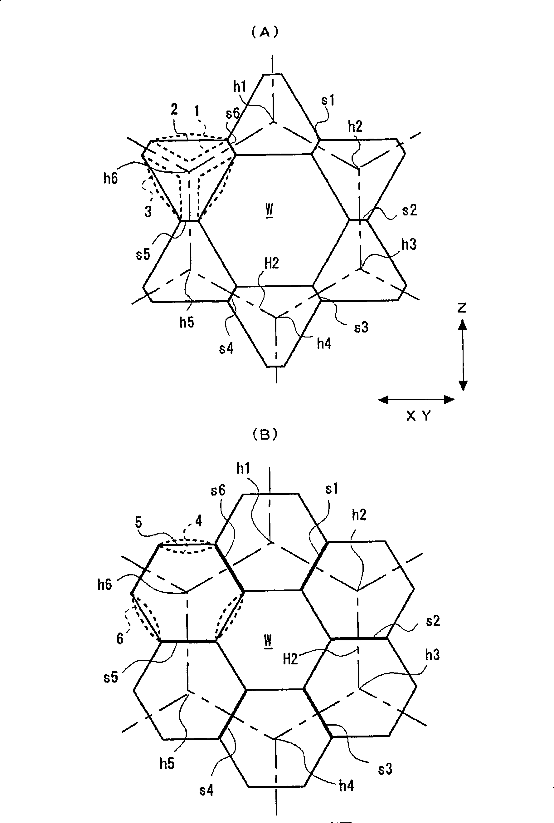
[0203] refer to Figure 15 Figure 21 , another embodiment of a building structure having a main frame with structural units connected to it arranged in a virtual honeycomb shape will be described.

[0204] Figure 15 It is a front view showing a part of the main frame 102 of the architectural structure constructed using structural units. For example with the above Figure 7 (A) Part of the same tubular architecture. Figure 16 yes Figure 15 A partially enlarged perspective view of the main frame 102 of FIG.

[0205] Figure 15 The main frame shown is constructed by arranging and connecting the structural units 2 shown in FIG.

[0206] A unit 2, such as Figure 15 As shown, it has a hexagonal plate surface with six sides when viewed from the front, and has a predetermined thickness (direction perpendicular to the paper surface). Thus, if Figure 16 As shown, there are six sides extending between respective sides of a pair of front and back panels. In the illustrate...

Embodiment 3

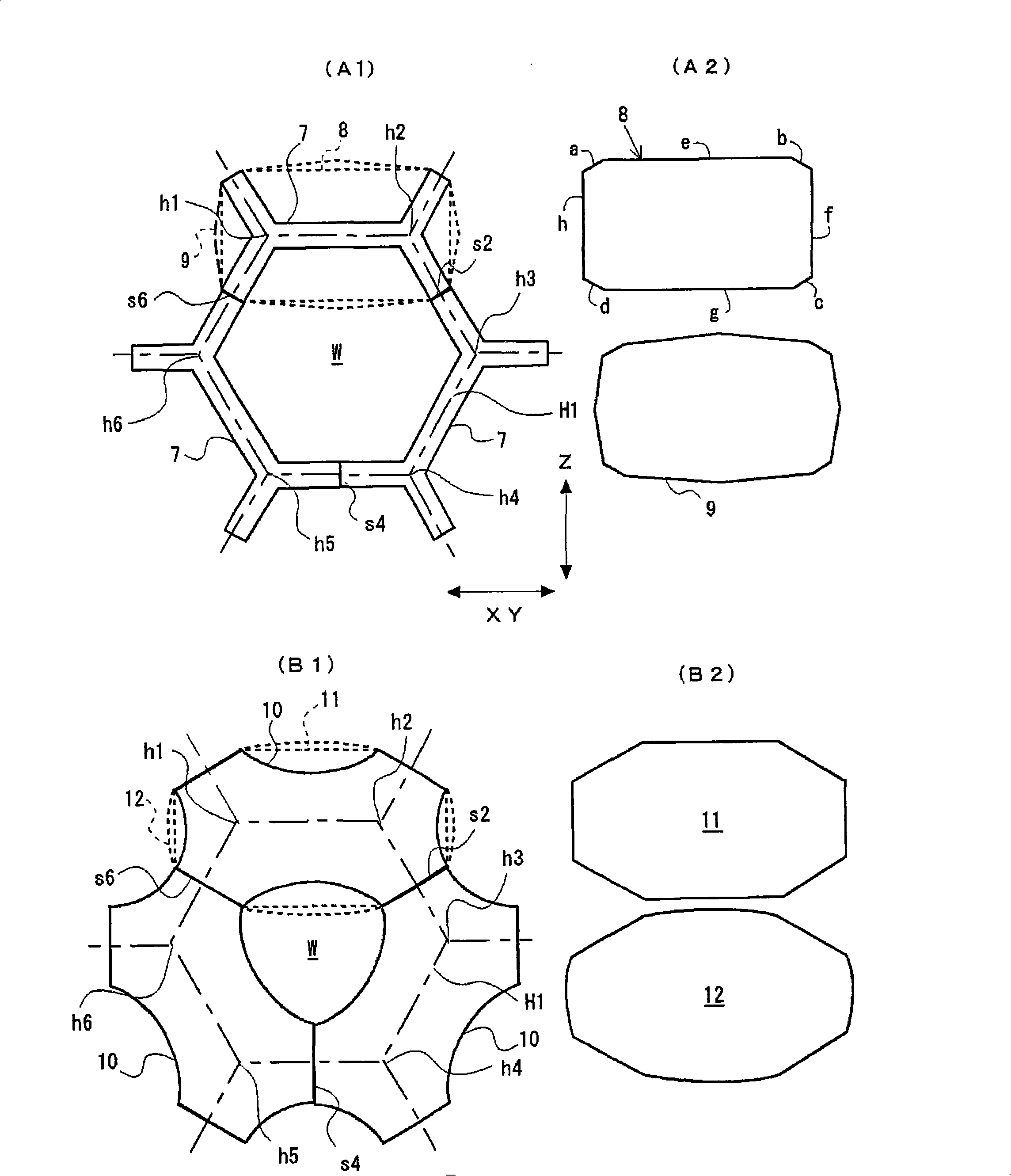
[0233] refer to Figure 22 to Figure 25 , another embodiment of a building structure having a main frame with structural units connected to it arranged in a virtual honeycomb shape will be described.

[0234] Figure 22It is a front view showing a part of the main frame 103 of the building structure constructed using structural units. For example with the above Figure 7 (A) Part of the same tubular architecture. Figure 23 yes Figure 22 A partially enlarged perspective view of the main frame 103 of FIG.

[0235] Figure 22 The main frame shown is for the figure 2 The hexagonal grid H2 shown (indicated by a thick dotted line) is used as a virtual honeycomb shape of the unit grid, and the connection is configured in the lower part K1 figure 2 Constructed with the structural unit 5 shown, the connection is configured in the upper part K2 figure 2 Constructed from the structural unit 4 shown. For Unit 5, follow the above Figure 19 In , it is described as a deformat...


PUM


Abstract

The present invention provides a construction structure body having a honeycomb-shaped main frame that is raised and extends in a planar form, a structure unit for the construction structure body, and a method for unit. The construction structure body has the main frame formed by connecting structure units with each other, and an imaginary honeycomb shape is raised and planarly extends in the structure body. In a plan view, structure units (1, 2, 3, 4, 5, 6) are individually placed at positions including vertexes (h1, h2, h3, h4, h5. h6) of a hexagonal grid (H1, H2) as a unit grid of the imaginary honeycomb shape. The construction structure body has means for rigidly joining two structure units with joint surfaces of the two structure units faced to each other, where each of the joint surfaces are formed at a portion on the outer peripheral surface of each of the two adjacent structure units. Each of the rigidly joined surfaces (s1, s2, s3, s4, s5, s6) intersects with one of the sides of the hexagonal grid, an opening (W) is formed at the center of the hexagonal grid, and the opening (W) is surrounded by all the structure units placed on the grid.

Description

technical field [0001] The present invention relates to a building structure constructed by interconnecting a plurality of structural units, and more particularly to a building structure having a honeycomb-shaped main frame extending planarly with hexagonal cells as unit cells. It also relates to the construction method of its structural unit and the building structure using it. Background technique [0002] Previously, several construction methods were known for constructing structural bodies using structural elements composed of prefabricated concrete parts. [0003] Patent Document 1 discloses a precast concrete member used in a dome-shaped architectural structure by joining triangular unit cells and its joining mechanism. In the architectural structure of Patent Document 1, six radial sides are separated from each vertex of a triangular lattice. As prefabricated concrete members for constructing the structure, a flat hexagonal joint member located at the center and six...

Claims


Application Information

Patent Timeline
Patent Type & Authority Applications(China)
IPC IPC(8): E04B1/35E04B1/20E04B1/22
CPCE04B1/34E04B1/18E04B1/22E04B2001/3583
Inventor 竹嶋一郎鸭下勉
Owner SEKISUI CHEM CO LTD
Why Eureka
Try Eureka