Blocking apparatus, gearbox drive unit containing a blocking apparatus such as this, as well as a method for production of a gearbox drive unit such as this

A locking device and drive unit technology, applied in electromechanical devices, electric vehicles, electrical components, etc., can solve the problems of unreliable transmission of locking torque, skew, noise, etc., to improve service life and continuous load capacity, reduce costs, The effect of high positioning accuracy

Inactive Publication Date: 2008-12-03
ROBERT BOSCH GMBH
View PDF1 Cites 7 Cited by
  • Summary
  • Abstract
  • Description
  • Claims
  • Application Information

AI Technical Summary

Problems solved by technology

Furthermore, there is the risk that the two brake elements are skewed relative to each other, as a r

Method used


Image

  • Blocking apparatus, gearbox drive unit containing a blocking apparatus such as this, as well as a method for production of a gearbox drive unit such as this
  • Blocking apparatus, gearbox drive unit containing a blocking apparatus such as this, as well as a method for production of a gearbox drive unit such as this
  • Blocking apparatus, gearbox drive unit containing a blocking apparatus such as this, as well as a method for production of a gearbox drive unit such as this

Examples


Embodiment Construction

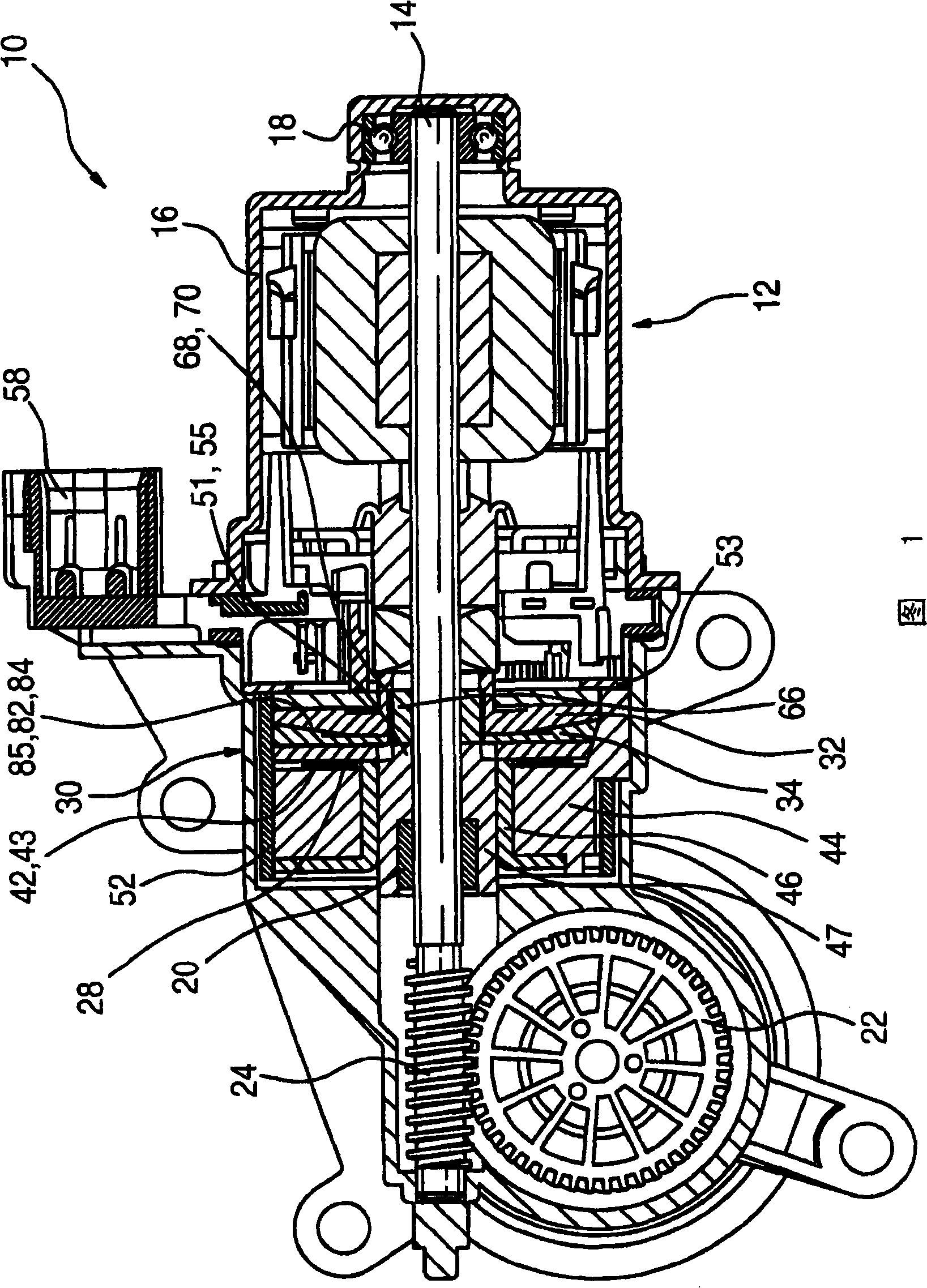
[0024]FIG. 1 shows a transmission drive unit 10 in which an electric motor 12 with a drive shaft 14 is arranged within a housing 16 of the transmission drive unit 10 . The drive shaft 14 is supported by means of rolling bearings 18 and / or slide bearings 20 and has a worm 24 which cooperates, for example via a worm gear 22 , with a not shown adjustment mechanism of the movable parts of the motor vehicle. In order to lock the drive shaft 14 relative to the housing 16 , a locking device 30 is arranged in the housing 16 , which has a first locking element 32 and a second locking element 34 . The first locking element 32 engages radially in a form-fitting manner into a catch 66 which is arranged in a rotationally fixed manner on the armature shaft 14 . In contrast, the second locking element 34 is connected in a rotationally fixed manner to the housing 16 of the transmission drive unit 10 . In the locked state (as shown in FIG. 1 ), the first locking element 32 snaps axially into ...


PUM


Abstract

Blocking apparatus, as well as a gearbox drive unit containing such a blocking apparatus, as well as a method for production of a gearbox drive unit such as this for blocking any rotary movement of a shaft (14) with respect to a housing (16) of a gearbox drive unit (10), having a first blocking element (32) and having a second blocking element (34) which can be moved axially with respect to the first blocking element (32) by means of an electromagnet (44) and at least one return element (42), in order to produce a connection between the first blocking element (32) and the second blocking element (34) such that they cannot rotate with respect to one another, with the electromagnet (44) having an inner pole (47) which is surrounded by an electrical coil (45), and with the inner pole (47) having an axial projection (51) which engages in a corresponding opening (64); in the second blocking element (34), for axial guidance and centring.

Description

technical field [0001] The invention relates to a locking device having two locking elements arranged displaceable relative to one another as well as to a transmission drive unit comprising the locking device and to a method of producing the transmission drive unit according to the preambles of the independent claims. Background technique [0002] A drive and / or brake device is known from EP 1 320 175 A2, wherein the brake unit is arranged within a housing surrounding the electric motor. The brake unit has a brake disk and a brake body, which can be pressed against each other in an electromagnetic friction fit. In this case, the brake body is connected in a rotationally fixed and axially fixed manner to the housing of the electric motor, while the brake disk is arranged axially displaceable on a rotatably mounted armature shaft of the electric motor. [0003] A brake device designed in this way has the disadvantage that many tolerances have to be compensated for in the asse...

Claims


Application Information

Patent Timeline
IPC IPC(8): H02K7/102F16D65/14
CPCY02T10/641
Inventor U·维尔特E·贝克U·雷特马P·克罗贝斯
Owner ROBERT BOSCH GMBH
Why Eureka
Try Eureka