

Vertical vacuum heavy pressure gas quenching furnace with rotatable material rest
Patent Information
- Authority / Receiving Office
- CN · China
- Patent Type
- Patents(China)
- Current Assignee / Owner
- SHENYANG HENGJIN VACUUM TECH
- Publication Date
- 2010-06-02
- Estimated Expiration
- Not applicable · inactive patent
Smart Images
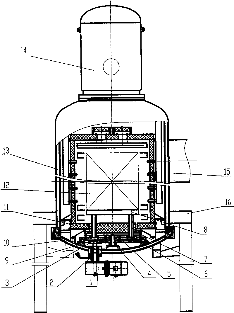
Figure 1 
Figure 2 
Figure 3
Abstract
Description
technical field
[0001] The invention relates to a high-pressure gas quenching furnace in metallurgical equipment, in particular to a vertical vacuum high-pressure gas quenching furnace with a rotatable material rack. Background technique
[0002] In the fields of military industry, aerospace and other processing technologies, the requirements for the uniformity of heating of the workpiece in the heat treatment process are getting higher and higher. However, in the vacuum high-pressure gas quenching furnace currently used, the workpiece is still in the furnace during high-temperature and high-vacuum operations. Due to the deviation of the furnace temperature, it is difficult to ensure consistent heating of the workpiece. Contents of the invention
[0003] The object of the present invention is to provide a vertical vacuum high-pressure gas quenching furnace with a rotatable material rack, so that the workpiece can be rotated during heating, which can ensure the heating unif...