Automatic measuring system of antenna phase center

An automatic measurement and antenna technology, applied in the field of measurement, can solve problems such as difficult operation, large calibration error, time-consuming and labor-intensive, etc., to achieve the effect of reducing error, ensuring safety, and programming the measurement process

Inactive Publication Date: 2008-12-10
XIDIAN UNIV
View PDF0 Cites 46 Cited by
  • Summary
  • Abstract
  • Description
  • Claims
  • Application Information

AI Technical Summary

Problems solved by technology

[0006] The purpose of the present invention is to solve the problems that the existing method for calibrating the antenna phase center requires continuous manual adjustment of the antenna position, human observation and judgment, time-consuming, laborious, difficult to operate, and large calibration errors. An automatic antenna phase center measurement system is proposed to realize Accurate calibration of the antenna

Method used


Image

  • Automatic measuring system of antenna phase center
  • Automatic measuring system of antenna phase center
  • Automatic measuring system of antenna phase center

Examples


Embodiment Construction

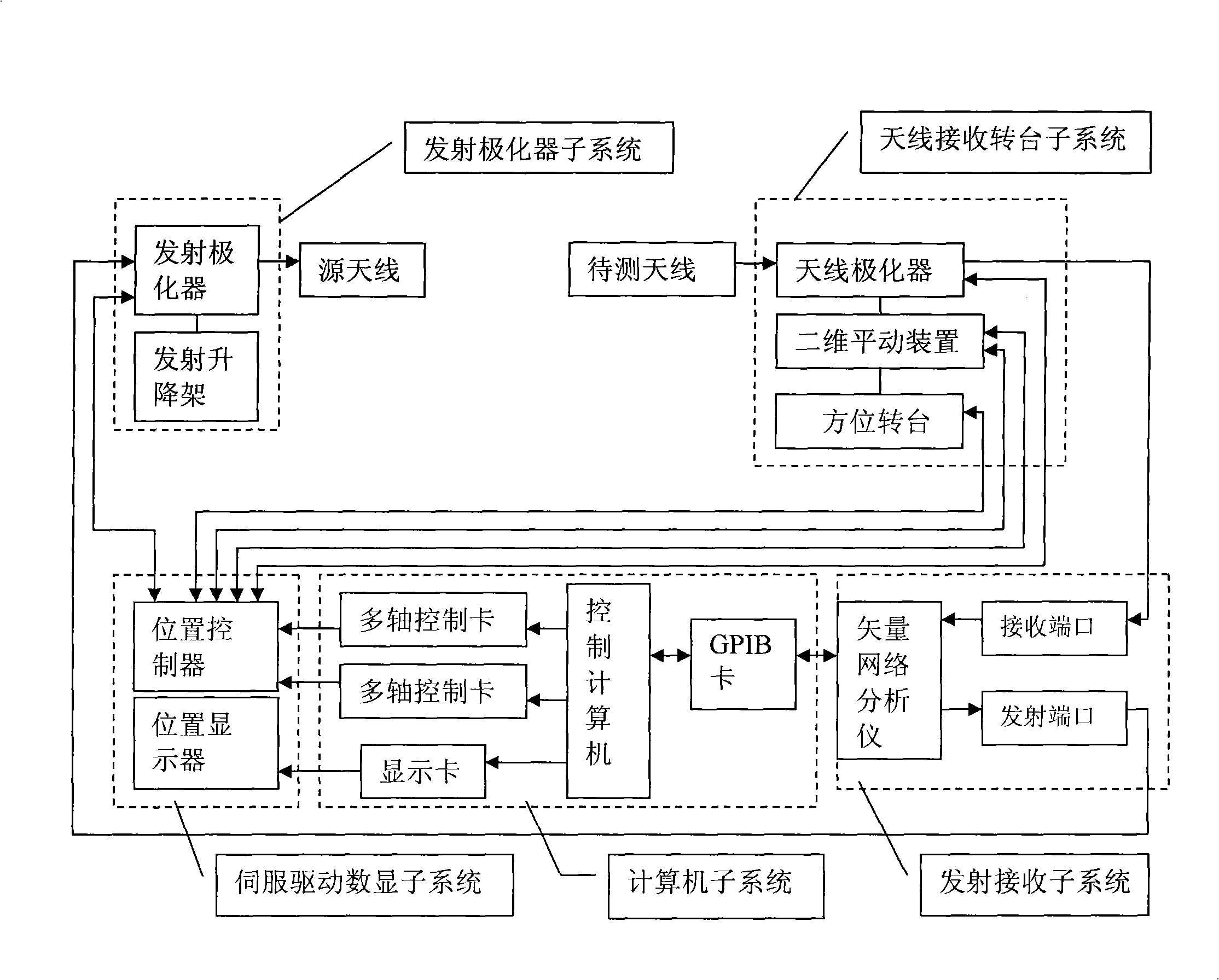
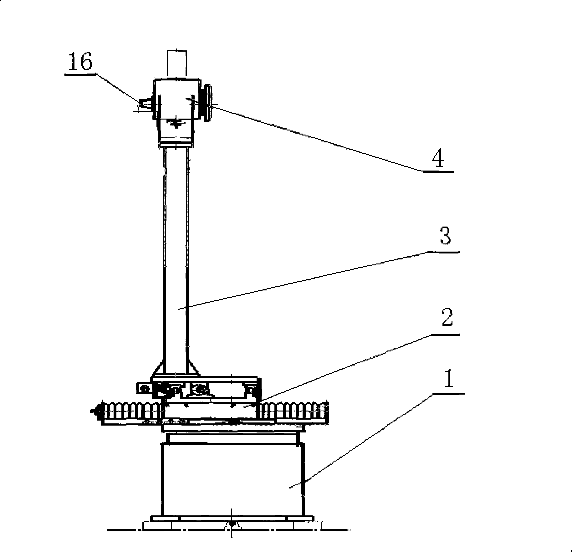
[0023] refer to figure 1 , the automatic test system of the present invention mainly includes five parts: antenna receiving turntable subsystem, transmitting polarizer subsystem, transmitting and receiving subsystem, servo drive digital display subsystem and computer subsystem. in:

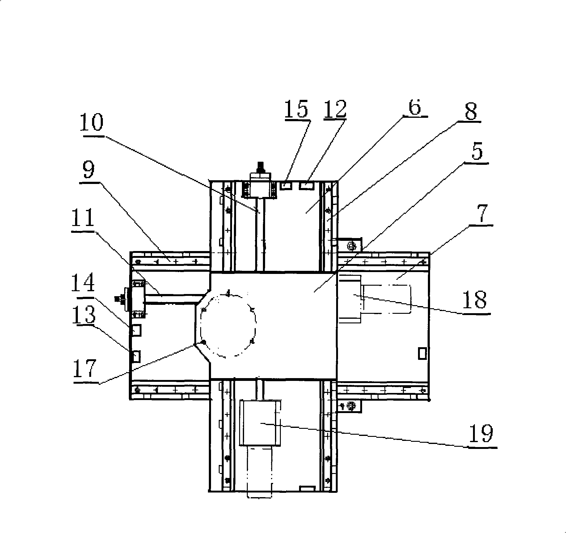
[0024] The antenna receiving turntable subsystem, such as figure 2 and image 3 . It is one of the key components of the measurement system. Its function is to install the antenna to be tested, precisely change the mechanical pointing of the antenna in space, and adjust the relative position of the antenna and the rotating shaft to accurately determine the phase center of the antenna. It is mainly composed of an azimuth turntable 1, a two-dimensional translation device 2, a bracket 3 and an antenna polarizer 4. The two-dimensional translation device 2 is located on the azimuth turntable 1 and is connected to the antenna polarizer 4 through a bracket 3 for Automatically adjust the position of ...


PUM


Abstract

The invention discloses an automatic measuring system in the center of an antenna phase, which comprises an antenna receiving rotary table subsystem, an emission polarizer subsystem, an emission and reception subsystem, a servo drive digital display subsystem and a computer subsystem. The antenna receiving rotary table subsystem and the emission polarizer subsystem are both connected with the emission and reception subsystem, the servo drive digital display subsystem and the computer subsystem; wherein, the antenna receiving rotary table subsystem consists of a direction rotary table (1), a two-dimensional translation device (2), a bracket (3) and an antenna polarizer (4). The two-dimensional translation device (2) is positioned between the direction rotary table (1) and the antenna polarizer (4) and used for automatically adjusting the positions of an antenna and the rotating axis of the direction rotary table, thereby making the phase center of the antenna near the axle center of the rotary table and ensuring the stable positions of the rotating axis of the direction rotary table and the rotating axis of the antenna polarizer when the direction rotary table is rotating. The automatic measuring system provided by the invention has the advantage of high measuring automation and can be used to accurately mark the phase centers of antennas.

Description

technical field [0001] The invention belongs to the technical field of measurement, and in particular relates to the measurement of the antenna phase center, which can be used for precise positioning of the antenna phase center. Background technique [0002] With the development of communication, radar, artificial satellite and aerospace technology, the requirements for the tracking and positioning accuracy of the antenna are getting higher and higher. The search and positioning of the amplitude beam alone cannot meet the requirements, and the phase center of the antenna must be used as the reference for accurate positioning. locate or measure. The phase center of the antenna is very important in many aspects, such as its phase measurement application, beam formation detection application, as an interferometer array unit and as a feed source of a parabolic antenna. The so-called antenna phase center is the equivalent radiation center of the antenna. For most antennas, ther...

Claims


Application Information

Patent Timeline
Patent Type & Authority Applications(China)
IPC IPC(8): G01R29/10
Inventor 尚军平付德民
Owner XIDIAN UNIV
Why Eureka
Try Eureka