Mechanico-hydraulic drive comprising a power split transmission

A technology of transmission device and driving mechanism, applied to the arrangement of multiple different prime movers of general power devices, power devices, transmission devices, etc.

Inactive Publication Date: 2008-12-10
BOSCH REXROTH AG
View PDF1 Cites 21 Cited by
  • Summary
  • Abstract
  • Description
  • Claims
  • Application Information

AI Technical Summary

Problems solved by technology

[0003] In the case of the drive train described, there is the disadv

Method used


Image

  • Mechanico-hydraulic drive comprising a power split transmission
  • Mechanico-hydraulic drive comprising a power split transmission
  • Mechanico-hydraulic drive comprising a power split transmission

Examples


Embodiment Construction

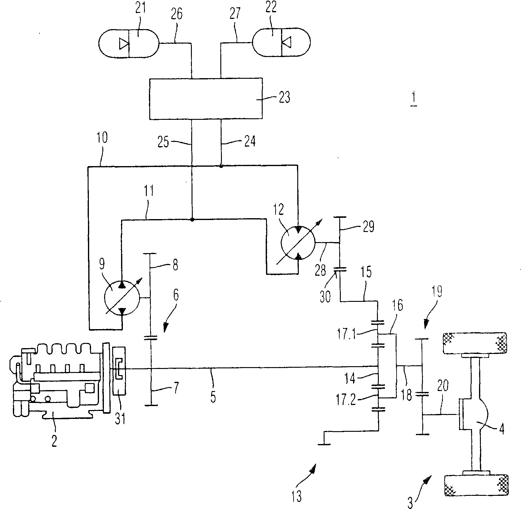
[0025] exist figure 1 In , a first embodiment of the drive mechanism according to the invention is shown. The split torque transmission 1 comprises a drive motor 2 via which an output shaft 3 of, for example, a wheel loader is driven. In the embodiment shown, this is a single driven shaft 3 . However, the gearboxes of all wheel drives can be driven very well by the torque split transmission 1 . The output shaft 3 has a differential 4 via which the wheels are driven.

[0026] The drive motor 2 can be connected to a drive shaft 5 through which the torque generated by the drive motor 2 is fed to the torque split transmission 1 . The hydraulic pump 9 is connected to the drive shaft 5 via the first transmission stage 6 . The first transmission stage 6 has a first spur gear 7 and a second spur gear 8 . The first spur gear 7 and the second spur gear 8 permanently mesh with each other so that the drive shaft 5 is permanently connected to the hydraulic pump 9 .

[0027] The hydra...


PUM


Abstract

The invention relates to a drive comprising a power split transmission (1). Said power split transmission (1) comprises a hydraulic pump (9) and a hydraulic engine (12) which are interconnected via a first working line (10) and a second working line (11). The drive also comprises at least one first storage element (21) for storing braking energy, the at least one first storage element (21) being linkable to the first working line (10) or the second working line (11). The hydraulic pump (9) and the hydraulic engine (12) are mechanically connected to an output shaft (18).

Description

technical field [0001] The invention relates to a drive with a split torque transmission and a storage element for storing braking energy. Background technique [0002] To drive a commercial vehicle, two drive trains are driven by a main drive motor in frequently used drive systems. A mechanical drive is used on the one hand and a hydrostatic drive in the other branch. In a hydrostatic drive, a hydraulic pump and a hydraulic motor work together to connect the hydraulic motor to the travel drive mechanism. Such a drive system is proposed in US 4,215,545. Its content is that the output shaft of the main drive motor can be connected via two clutches to a mechanical branch or a hydraulic pump. The hydraulic pump is connectable to the hydraulic motor via a first operating line and a second operating line. In order to be able to reverse the direction of flow, there are distribution valves that can alternate the connection between the hydraulic motor and the hydraulic pump. In...

Claims


Application Information

Patent Timeline
IPC IPC(8): B60K6/12F16H47/04F16H3/72
CPCB60K6/12B60T1/10B60Y2200/41F16H47/04F16H61/4096F16H61/4157F16H2037/088Y02T10/62
Inventor 马蒂亚斯·穆勒斯蒂芬·穆彻勒
Owner BOSCH REXROTH AG
Why Eureka
Try Eureka