
Fluid compressor with aerostatic bearing, control system of a compressor with aerostatic bearing and method of controlling a compressor with aerostatic bearing

A compressor, statics technology, applied in the components, bearings, pump control, etc. of pumping devices for elastic fluids, can solve the problems of cost, production and maintenance, etc.

Inactive Publication Date: 2008-12-10
WHIRPOOL SA
View PDF1 Cites 10 Cited by
  • Summary
  • Abstract
  • Description
  • Claims
  • Application Information

AI Technical Summary

Problems solved by technology

[0007] One of the disadvantages of this solution is that it requires the assembly of reservoirs and lines, which creates costs for manufacture and maintenance

Method used


Image

  • Fluid compressor with aerostatic bearing, control system of a compressor with aerostatic bearing and method of controlling a compressor with aerostatic bearing
  • Fluid compressor with aerostatic bearing, control system of a compressor with aerostatic bearing and method of controlling a compressor with aerostatic bearing
  • Fluid compressor with aerostatic bearing, control system of a compressor with aerostatic bearing and method of controlling a compressor with aerostatic bearing

Examples


Embodiment Construction

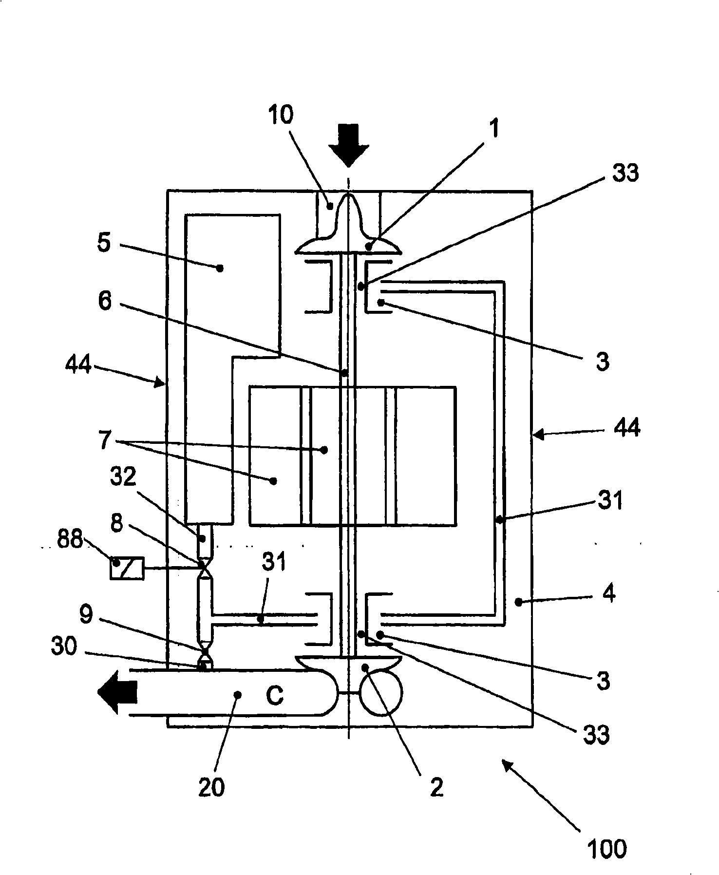
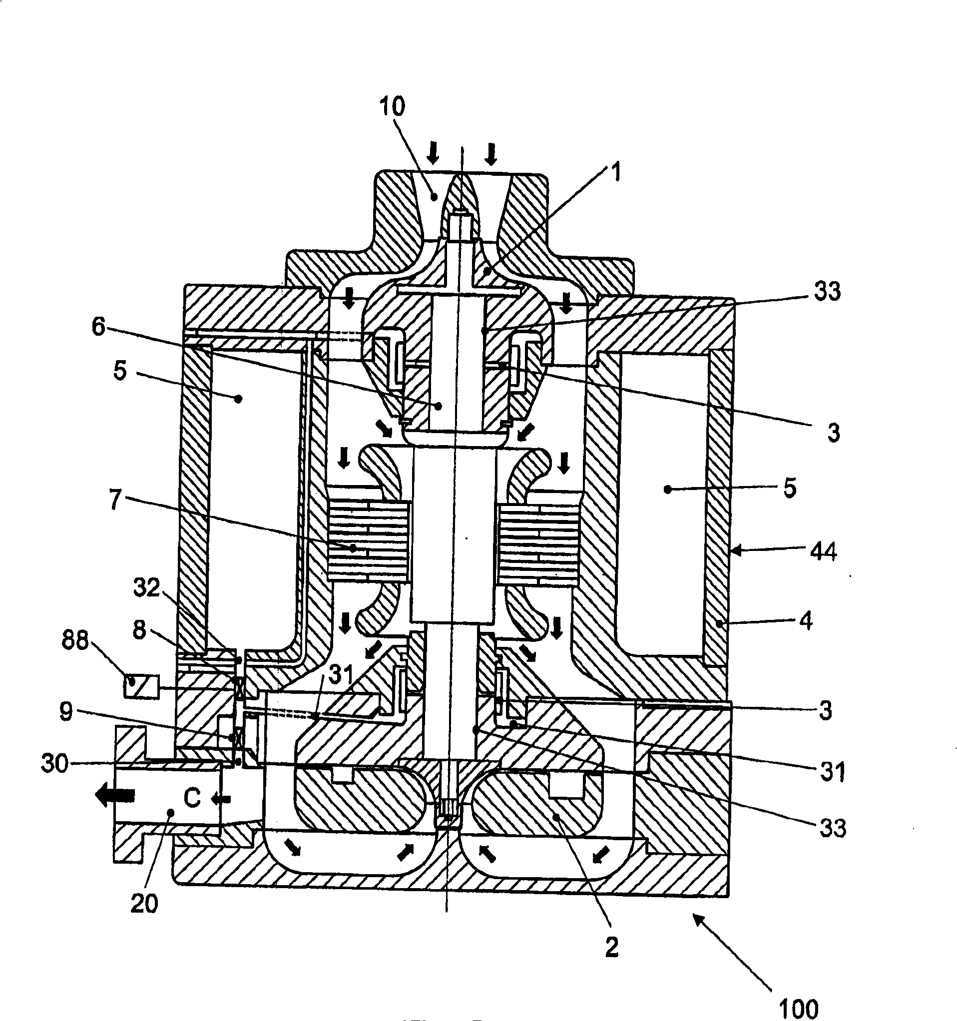
[0022] as from figure 1 and figure 2 As can be seen in , one of the possible embodiments of the teachings of the present invention is their application to centrifugal compressors, for example of the two-stage type. This type of compressor has two stages, the compressor rotor 1 of the first stage of the compressor has the function of drawing fluid (gas) through the non-pressurized inlet 10; The pressure port 20 is used for a cooling circuit (not shown). The two compression rotors 1 , 2 are related, in other words they are fixed mechanically at the end of the same shaft 6 , which in turn is activated by an electric motor 7 . The shaft 6 also has a pair of aerostatic bearings 3 in the floating pressurized region 33, the aerostatic bearings 3 begin to float when subjected to positive pressure.

[0023] In addition, the compressor 100 further comprises a housing 4 comprising an outer or closing wall 44 hermetically enclosing the compressor 100 .

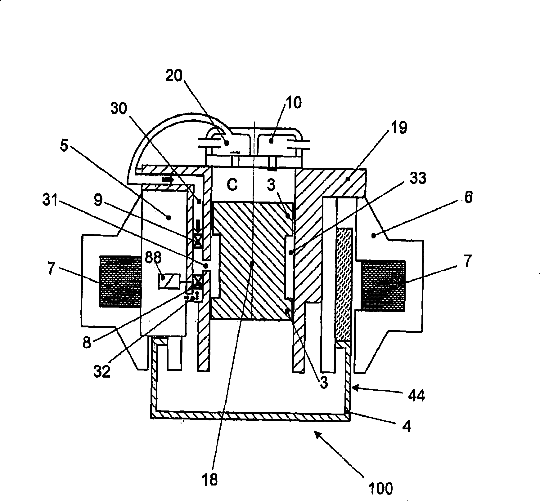
[0024] Another embodiment of ...


PUM


Abstract

The present invention relates to a fluid compressor having an aerostatic bearing, to a control system of a fluid compressor having an aerostatic bearing as well as to a method of controlling a compressor, wherein the aerostatic bearing is fed by a compressed fluid accumulator (5) which is charged during the operation of the compressor (100) and discharged at the respective start to prevent damage to the bearings.; These objectives are achieved by means of a fluid compressor (100) comprising a pressurization chamber (C) and at least one fluid pressurization device (1, 2, 18), the pressurization chamber (C) and the pressurization device (1, 2, 18) being located in a housing (4), the pressurization chamber (C) having a non- pressurized inlet (10) and a pressurized outlet (20), the pressurization device (1, 2, 18) compressing the fluid collected by the non-pressurized inlet (10) and discharging it through the pressurized outlet (20), the pressurization device (1 , 2, 18) having at least one aerostatic bearing (3), the aerostatic bearing (3) comprising a floating pressurization region (33), the compressor comprising a compressed fluid accumulator (5) fluidically connectable to the pressurized outlet (20) and the floating pressurization region (33), the compressed fluid accumulator (5); being located inside the housing (4) of the compressor (100). A system for controlling a compressor (100) and the respective control method are further described.

Description

technical field [0001] The present invention relates to a fluid compressor with an aerostatic bearing, a control system for a fluid compressor with an aerostatic bearing and a control method for the compressor. The fluid compressor may include, for example, a centrifugal compressor or a linear compressor applicable to a cooling system. Compressors and pressurized structures within the bearings of the equipment and various control systems. Background technique [0002] Centrifugal compressors have long been used in industry, for example in the automotive industry. The concept is rather simple compared to other compressors such as reciprocating compressors, rotary compressors, etc. However, the bearing system of the centrifugal compressor is very complicated due to the high speed operation during the normal function mode, which is estimated to rotate at about 30000 to 200000 rpm. Apparently, due to the technical difficulties of the bearing system, the use of centrifugal comp...

Claims


Application Information

Patent Timeline
Patent Type & Authority Applications(China)
IPC IPC(8): F04D29/04F04D15/00F16C32/06
CPCF04D29/057F16C32/0614F04D29/056F05D2260/85F04D29/052
Inventor M·F·伊特卡
Owner WHIRPOOL SA
Learn More