

Method for controlling clutch in vehicle transmission system equipped with friction type stepless speed changer
A friction clutch, clutch technology, applied in the direction of clutch, mechanical equipment, etc., can solve the problem of inability to distinguish clutch slip, complexity, and the weakening ability of the clutch to suppress torque vibration.
- Summary
- Abstract
- Description
- Claims
- Application Information
AI Technical Summary
Problems solved by technology
Method used
Image

Examples
Embodiment Construction
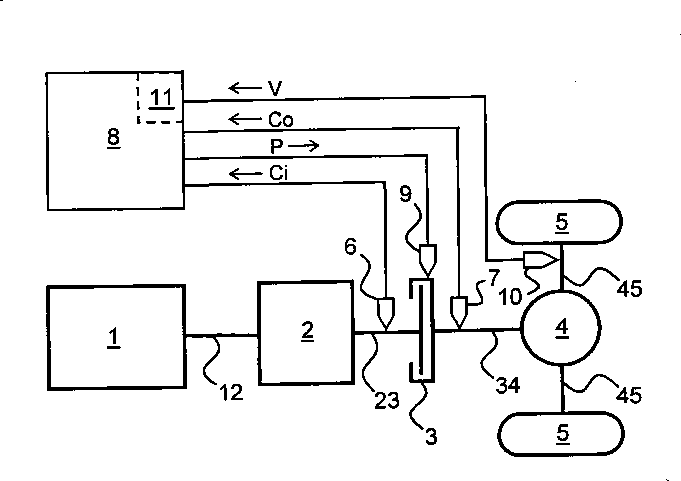
[0015] figure 1 A vehicle drive train is described which includes, in order (ie, in the direction downstream of the driving force) an engine 1, a frictional continuously variable transmission 2, a friction clutch 3, a final drive 4 including a differential transmission and two driven wheels 5. The transmission shafts 12, 23, 34 and 45 are provided between and drivingly connected with the components 1-5 of the upper transmission train. figure 1 A clutch slip control device is also schematically shown in , which includes two speed sensors 6 and 7, which measure the speed Ci on the input side of the clutch (ie, shaft 23) and the speed Co on the output side of the clutch (ie, shaft 34). An electronic clutch control unit 8 or "ECCU" and a clutch actuator 9 which controls the action of the clutch 3 (eg by adjusting the hydraulic clutch engagement pressure P).
[0016] From this, it is known that the ECCU 8 is set and operated such that the desired clutch slip amount Cs is reached ...
PUM
 Abstract
Description
Claims
Application Information