Motor and control device therefor

A control device, stator pole technology, applied in the direction of motor control, AC motor control, electromechanical devices, etc., can solve the problems of power factor torque ripple increase, noise, inverter size increase, etc.

Pending Publication Date: 2021-06-11
梨木政行
View PDF3 Cites 0 Cited by
  • Summary
  • Abstract
  • Description
  • Claims
  • Application Information

AI Technical Summary

Problems solved by technology

The second problem is that in the vicinity of the maximum torque of the motor, the power factor is low and the size of the inverter increases
In particular, as a motor for the main engine of an electric vehicle, a large torque of more than three times the continuous rated torque is required, and the problems of power factor and torque ripple increase.
[0013] The third problem is that the time ratio and space ratio of torque generated by each part constituting the reluctance motor are different. Figure 83 as low as around 33% (1 / 3) in the example of
In addition, there are problems of noise, torque ripple, etc.

Method used


Image

  • Motor and control device therefor
  • Motor and control device therefor
  • Motor and control device therefor

Examples


Embodiment 1

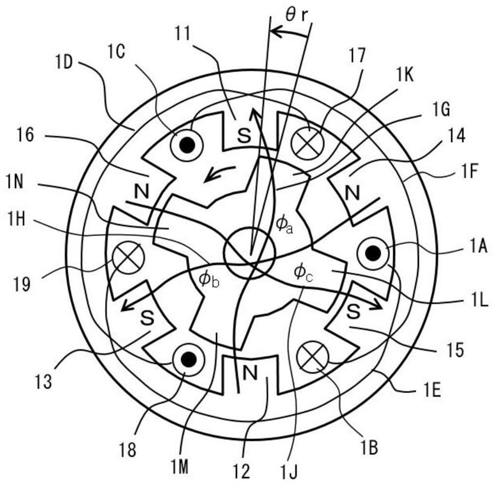
[0153] figure 1 An example of a transverse cross-sectional view of the magnetoresistance motor of the present invention is shown. figure 1 The circumferential direction of the stator magnetic poles 11, 12, 13, 14, 15, 16 is 30 °, and the equal intervals are disposed in six places of the whole circle. The rotor magnetic poles 1K, 1L, 1M, and 1N have a circumferential direction of 30 °, equal intervals are disposed in four places of the entire circumference. figure 1 The shape of the stator magnetic pole and the rotor magnetic pole and the above Figure 83 The magnetic pole shape is the same. figure 1 The purpose of the composition is to increase the cross-sectional area of ​​each winding in the groove to 2 times, and the copper damage in the groove is lowered.

[0154] for figure 1 Each winding is shown Figure 83 The concentrated windings of the respective stator magnetic poles shown are converted to a full length scaner winding, and two concentration windings in each slot are comb...

Embodiment 2

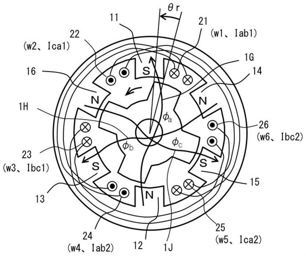
[0329] Next, other embodiments of the first aspect of the driving circuit Figure 7 Shown and described. exist figure 1 Motor, the number of full-pitch windings as few as three, is an odd number, in the case of two windings connected in series and each of the energization method, requires an asymmetrical portion, the load generated on the circuit. In order to eliminate the burden on such a circuit, such as figure 2 , There is shown a set of phase windings each connected in parallel constituting the winding, and is set by six windings Image 6 The exemplary drive circuit driving. exist Image 6 In each phase the voltage and current is driven into two groups, thus increasing the number of transistors is six, but no load on the above-described circuit, the current value of 1 / 2 of each of the transistors, the current of all the transistors the total capacity of a small value, when simply considering logically, the inverter can be downsized.

[0330] Figure 7 Direct drive figure 1 The me...

Embodiment 3

[0336] Next, other embodiments of the first aspect of the driving circuit Figure 8 Shown and described. Above Figure 7 , Image 6 , The new increase of transistor 81 and diodes 82,83,84. exist Figure 8 Drive circuit, B-phase current component Ib from the transistor 61 through the AB-phase full-pitch winding 67 through the diode 84, transistor 81 be passed through. Another B-phase full-pitch current component Ib through transistor 63 from the BC phase winding 69 through diode 83, transistor 81 be passed through. By the transistor 81 through the parallel windings 67 and the B-phase current component 69 Ib. In this case, if Figure 14 Voltage illustrated example, by a change in magnetic flux through the other adverse effects caused by large phase voltage, but the voltage of transistor 81 is twice configuration can be applied to the two windings, voltage problems can be eliminated. Smaller voltage interference. However, since the transistor 81 through the parallel component B-phase curr...


PUM


Abstract

To reduce the size and cost of a motor and a control device. The present invention relates to a motor for appropriately supplying one-way current to each of winding wires, and a circuit for driving the motor. Two full-pitch winding wires Wab and Wca, respectively disposed adjacent to each side of an A-phase stator magnetic pole, and driving transistors are connected to each other in series to supply A-phase current component Ia, an A-phase magnetic flux component [[phi]a passing through the A-phase stator magnetic pole is excited to generate torque, and the other phases are configured in the same manner. As a result, each of the stator magnetic poles can be selectively excited, and the voltages at both ends of the series winding wire are reduced to the corresponding magnetic flux, thus simplifying and improving the performance of the motor. In addition, since each of the winding wires and each of the transistors can be commonly used in two phases, the utilization rate can be improved, and size and cost reductions can be achieved.

Description

Technical field [0001] The present invention relates to one kind of the motor rather than direct current into alternating current into the alternating current motor, i.e. each winding is appropriately directed into a unidirectional current motor and its drive circuit, a control means. Thus, the current magnetomotive force generated by the windings of the stator acts only on a direction of each stator pole. [0002] Further, although the present invention is an improvement of reluctance motor and a conventional control apparatus, development, but, for example, the present invention further comprises a permanent magnet rotor driven efficiently through unidirectional current technology. [0003] The present invention relates to the use of the host vehicle EV electric motor, motor home appliances, industrial motors and the like. Make high performance, high efficiency, miniaturization, weight reduction, cost reduction technique involves. Background technique [0004] AC motor is the c...

Claims


Application Information

Patent Timeline
Patent Type & Authority Applications(China)
IPC IPC(8): H02P25/08H02K19/10H02K21/14H02P25/024
CPCH02K37/04H02K37/06H02K16/02H02K2213/03H02P25/092H02P2207/05H02K19/06Y02T10/64H02K1/146H02K3/28
Inventor 梨木政行
Owner 梨木政行
Why Eureka
Try Eureka