Motor and control device therefor

a control device and motor technology, applied in the direction of synchronous motors, magnetic circuit shapes/forms/construction, synchronous motors, etc., can solve the problems of increasing the size of the motor, reducing the service life of the motor, so as to achieve easy application of current, high torque, and simplified over-voltage characteristics.

Pending Publication Date: 2022-04-14
NASHIKI MASAYUKI
View PDF0 Cites 0 Cited by
  • Summary
  • Abstract
  • Description
  • Claims
  • Application Information

AI Technical Summary

Benefits of technology

[0212]A novel technique of the present invention provides a motor comprising a full pitch winding that carries a unidirectional current. In this motor, excessive and complicated voltage characteristics are simplified, current is easily applied, and high torque and high power factor are realized. In addition, the winding is shared by using the full pitch winding, and the motor loss is reduced. As a result, the continuous rated torque and the maximu

Problems solved by technology

However, changing the viewpoint, AC motors have some inconveniences.
That is, it is a problem related to the motor configuration and the operation description.
The first problem of the conventional reluctance motor is that the continuous rated torque is inferior to that of the permanent magnet type synchronous motor having the same motor size.
This causes a problem that the size of the motor increases and the weight increases.
Copper loss is dominant in motor loss at low speed rotation.
The second problem is that the power factor is low in the vicinity of the maximum torque of the motor and the size of the invert

Method used


Image

  • Motor and control device therefor
  • Motor and control device therefor
  • Motor and control device therefor

Examples


tenth embodiment

[0505]Next, another embodiment according to claim 1 is shown in the cross-sectional view of FIG. 19 and the drive circuit of FIG. 20. FIG. 19 illustrates a reluctance motor having eight stator magnetic poles and six rotor magnetic poles. FIG. 19(a) shows a conventional reluctance motor, which uses a centralized winding. FIG. 19(b) exemplifies a reluctance motor in which full pitch winding windings in parallel are wound in each slot. The reason for arranging the windings in parallel is the same as in the case of the configuration shown in FIG. 2. This motor is driven using the circuit shown in FIG. 20. The windings on both sides of each stator pole are connected in series and a current is applied. Therefore, when each stator magnetic pole is excited, the interlinkage magnetic fluxes of the other phases are canceled out and are not affected by the interlinkage magnetic flux.

[0506]In FIG. 19(a), reference numeral 901 is an A5 phase stator magnetic pole, and reference numeral 902 is an ...

eleventh embodiment

[0563]Next, another embodiment of the drive circuit according to claim 1 will be described with reference to FIG. 21. In the case of the drive circuit of FIG. 20, a configuration is adopted in which two sets of currents of each phase can be energized, the symmetry of the circuit is maintained, and each transistor can be driven efficiently. The total current capacity of the transistor is small. However, since two sets of currents in each phase are energized, there is a disadvantage that the number of transistors increases to 10. Therefore, FIG. 21 shows an example of another drive circuit. This drive circuit adopts a configuration in which one transistor is added to compensate for the asymmetry of the circuit, and one set of full pitch windings of each phase shown in FIG. 19(b) is completed. That is, the number of full pitch winding windings shown in FIG. 19(b) is four. The number of transistors is “(10) / 2+(1)”=6.

[0564]In the drive circuit configuration shown in FIG. 21, the right ha...

thirteenth embodiment

[0585]Next, another embodiment of claim 1 is shown in the cross-sectional view of FIG. 25 and the drive circuit of FIG. 26.

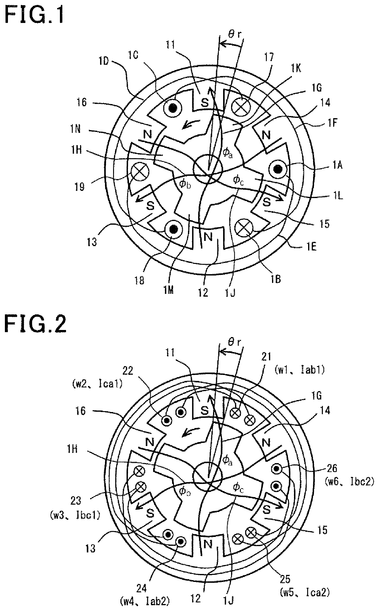
[0586]In the motor configuration according to this embodiment, the number of stator magnetic poles is 10, and the number of rotor magnetic poles is 6. The circumferential width of each magnetic pole is about 18°. In a specific example described later according to this embodiment, the magnetic pole width is exemplified by 24°. In FIG. 25(a), the winding of the motor acts as a centralized winding. In FIG. 25(b), the winding of the motor is a full pitch winding. For efficient drive, the full pitch winding wound between the two slots is separated into two parallel full pitch windings.

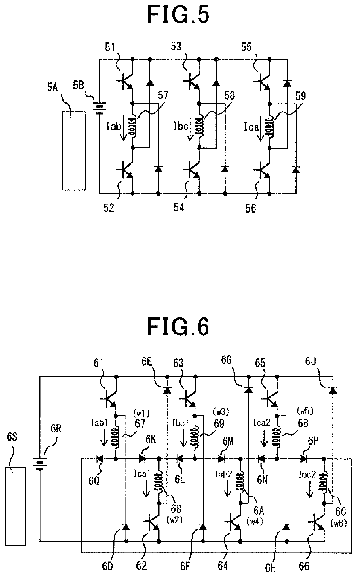
[0587]As described above, in the combination of the motor shown in FIG. 2 and the drive circuit shown in FIG. 6, six stator magnetic poles are illustrated. When the number of stator magnetic poles is 6, 10, 14, 18, 22, or the like, the drive circuit shown in FIG. 6 may be increased by t...


PUM


Abstract

A motor has windings and a control device, which applies appropriately one-way current to each of the windings. Two full-pitch windings, which are located adjacently to both ends of an A-phase stator magnetic pole, and driving transistors are connected in series to each other to supply an A-phase current component, thereby exciting an A-phase magnetic flux component passing through the A-phase stator magnetic pole, resulting in generation of torque. This excitation is also applied to other phases. The respective stator magnetic poles can be excited selectively, and voltages across both ends of the serially connected windings become a voltage for corresponding magnetic flux components which should be provided by the windings, thus providing a more simplified motor structure and higher motor performance. The windings and transistors can be used commonly in two phases, providing an improved usage rate, thus making the motor more compact in size and reducing manufacturing cost.

Description

TECHNICAL FIELD[0001]The present invention relates to an AC electronic motor energized with AC currents as well as a DC electric motor energized with a DC current, that is, relates to an electric motor having windings to which one-way current(s) is supplied in a controlled manner, a drive circuit and a control apparatus which are for the motor. Accordingly, the motor includes a stator with windings energized with current in which the currents generate magnetomotive forces which operate only in one way path of each stator magnetic poles. The motor and control apparatus according to the present invention are improved and developed compared to the conventional reluctance motor and control apparatus, and, for instance, the prevent invention provides a technique of driving a permanent magnet rotor efficiency by the one-way current(s).[0002]Applications to which the present invention can be applied are for main engine motors of electric vehicles, motors of home electric appliances, motors...

Claims


Application Information

Patent Timeline
IPC IPC(8): H02K1/14H02K3/28H02P25/092
CPCH02K1/146H02K2213/03H02P25/092H02K3/28H02K37/04H02K37/06H02K16/02H02P2207/05H02K19/06Y02T10/64
Inventor NASHIKI, MASAYUKI
Owner NASHIKI MASAYUKI
Why Eureka
Try Eureka