Method for inspecting the state of a rotating machine drive shaft

A technology of rotary machinery and drive shafts, which is applied in the direction of vibrating fluids, measuring devices, and sound-generating devices, and can solve problems such as interference and attenuation of transmitted and received energy

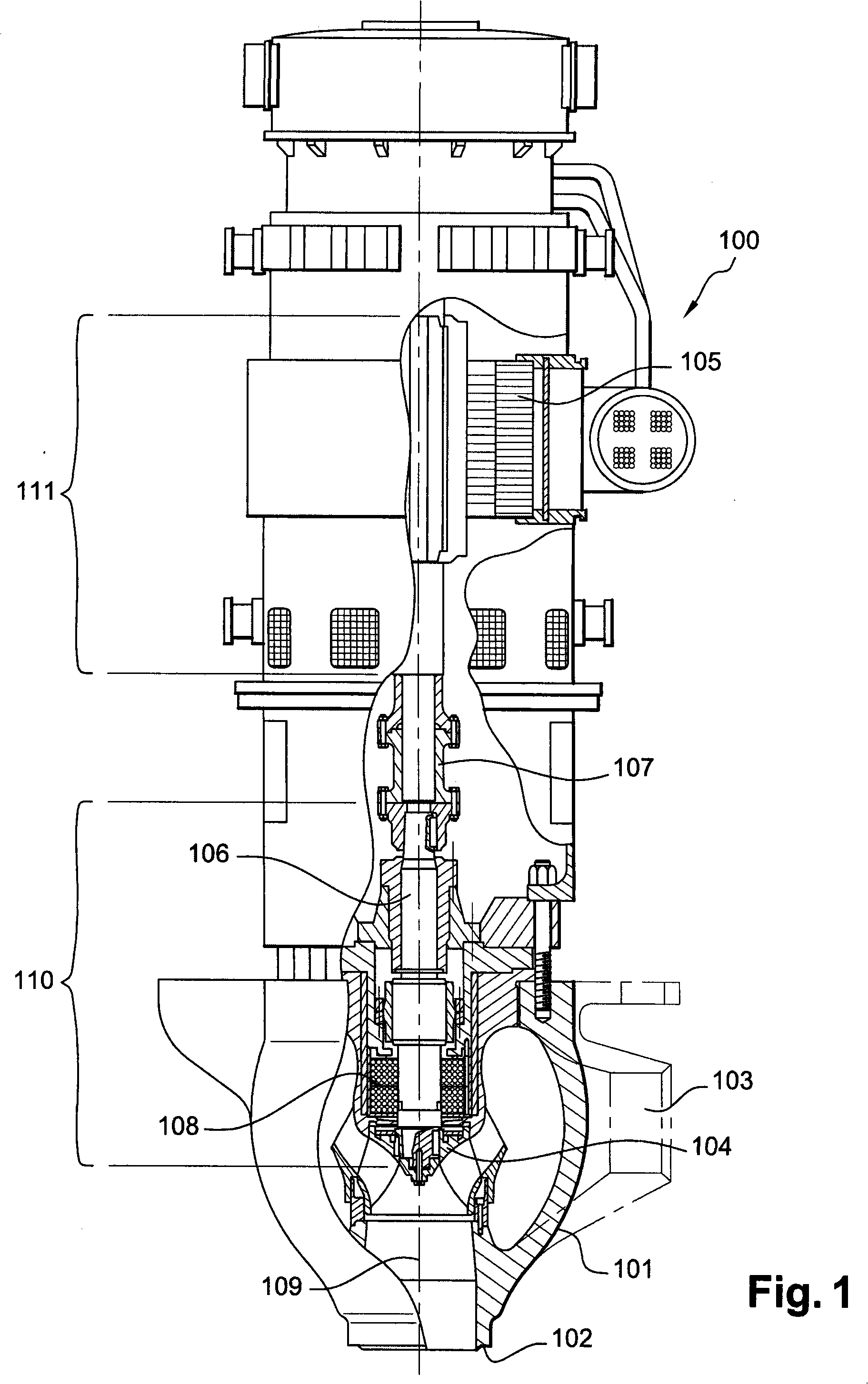
Inactive Publication Date: 2008-12-10
FRAMATOME ANP
View PDF0 Cites 2 Cited by
  • Summary
  • Abstract
  • Description
  • Claims
  • Application Information

AI Technical Summary

Problems solved by technology

This characteristic leads to interference and attenuation of the transmitted and received energy of the above-mentioned conventional sensors

Method used


Image

  • Method for inspecting the state of a rotating machine drive shaft
  • Method for inspecting the state of a rotating machine drive shaft
  • Method for inspecting the state of a rotating machine drive shaft

Examples


Embodiment Construction

[0058] In the method according to the invention, the electronic focusing principle and the electronic deflection principle, as shown in FIGS. 6 and 7 respectively, are used in order to test the state of the drive shaft.

[0059] In the example shown in FIG. 6 , the principle of electronic focusing consists in using an electronic delay applied in the transmission to the individual elements 600 that make up the line sensor 601 . The law of delay 602 - or the law of focus - is applied to a group 604 of individual sequential elements 600 . In general, the law of time delay applied to multi-element sensors consists in delivering a single electrical pulse distributed over several channels, each channel terminating at a different element of the sensor in question, each channel also having multiple capacitances or inductive type devices, which cause a delay specific to the output of the channel in question.

[0060] The law of time delay 602 consists in initially emitting the ultraso...


PUM


Abstract

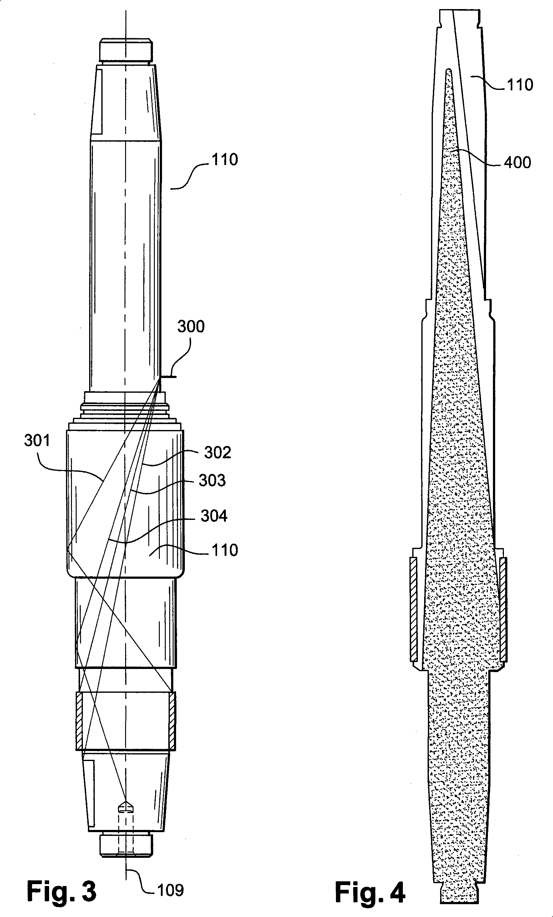
The invention relates to a method for non-distructive testing of a drive shaft (110), which is accessible from one end thereof, by means of an annular ultrasonic multi- element longitudinal wave transducer (900;1000) comprising independent elements excitable by equifrequent electric pulses for which the inventive method consists in applying different electronic phase shiftings to the pulses transmitted thereto. Said electronic phase shifting makes it possible to focus or deviate a final beam which is synthesised by the totality of elements forming the transducer and to concentrate said final beam in such a way that a generally cylindrical cross-section thereof substantially smaller than the testable shaft cross-section is adopted and is highly energetic at a long distance by a wave guide action produced by the cylindrical shape of the shaft.

Description

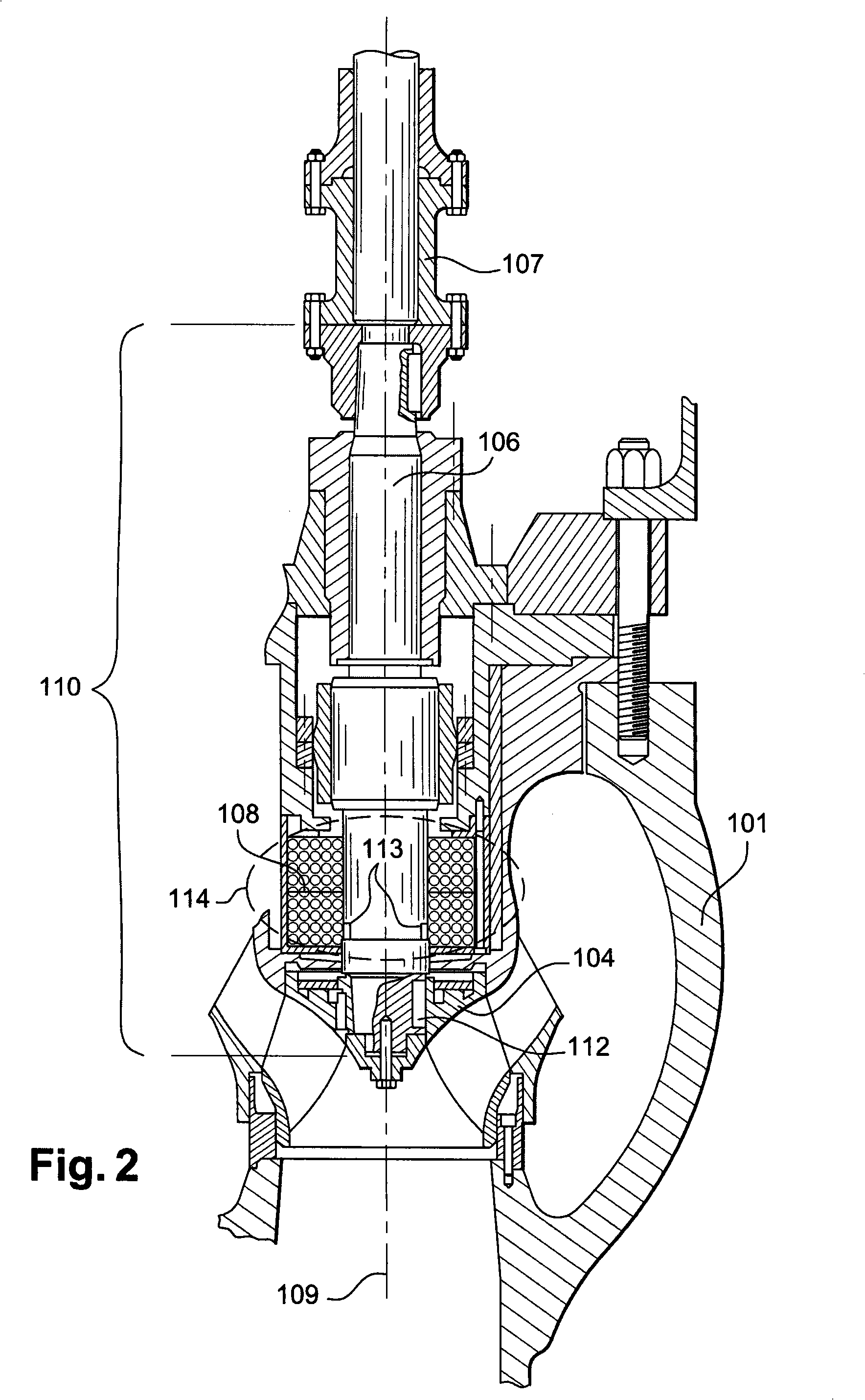
technical field [0001] The invention relates to a method for controlling the state of a drive shaft of a rotary machine. The purpose of the invention is mainly to propose a solution for performing a non-destructive test of the state of a drive shaft, one end of which can be used to perform said test. Background technique [0002] The invention will be described in more detail with reference to a nuclear reactor main pump comprising in particular an impeller driven by an electric motor through a drive shaft to be tested. However, the method according to the invention may be used to test the condition of any solid shaft, particularly carbon steel or stainless steel shafts used in rotating machinery subjected to thermal, mechanical or other stresses that could damage said shaft. [0003] A more detailed description of the field of use of the method according to the invention is that of the main pumps of nuclear reactors cooled by pressurized water. An example of such a pump c...

Claims


Application Information

Patent Timeline
Patent Type & Authority Applications(China)
IPC IPC(8): G01N29/26G01N29/265G01N29/34G01N29/04G01N29/24G10K11/34B06B1/06
CPCG01N29/043G01N29/2456G01N29/262G01N29/265G01N29/341G01N2291/0421G01N2291/0422G01N2291/106G01N2291/269G01N29/26G01N29/24G01N29/34
Inventor 奥利佛·皮埃尔·碧哈让·约瑟夫·卡瓦利尔
Owner FRAMATOME ANP
Why Eureka
Try Eureka