Light pen input system and method, particularly for use with large area non-CRT displays

An input system and light pen technology, applied in the input/output of user/computer interaction, the input/output process of data processing, instruments, etc., can solve expensive problems, achieve low cost and increase simplicity

Inactive Publication Date: 2008-12-10
KONINKLIJKE PHILIPS ELECTRONICS NV
View PDF1 Cites 9 Cited by
  • Summary
  • Abstract
  • Description
  • Claims
  • Application Information

AI Technical Summary

Problems solved by technology

However, the photosensitive elements required

Method used


Image

  • Light pen input system and method, particularly for use with large area non-CRT displays
  • Light pen input system and method, particularly for use with large area non-CRT displays
  • Light pen input system and method, particularly for use with large area non-CRT displays

Examples


Embodiment Construction

[0050] In the following, elements with similar or identical functions will have the same reference signs.

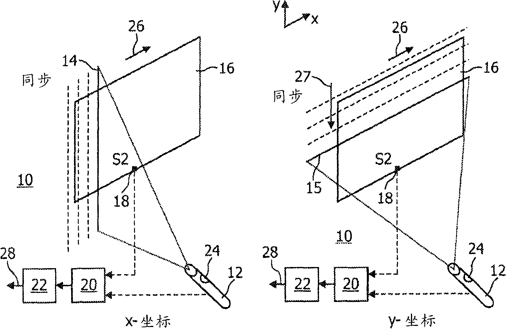
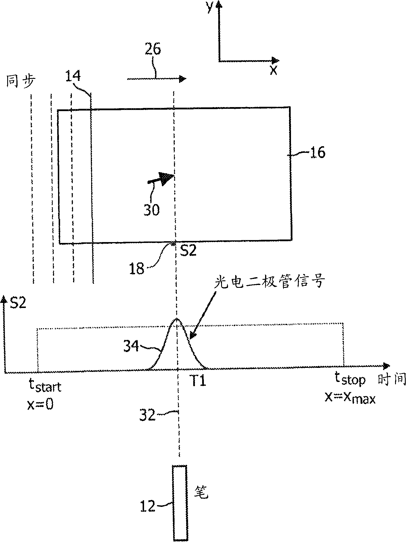
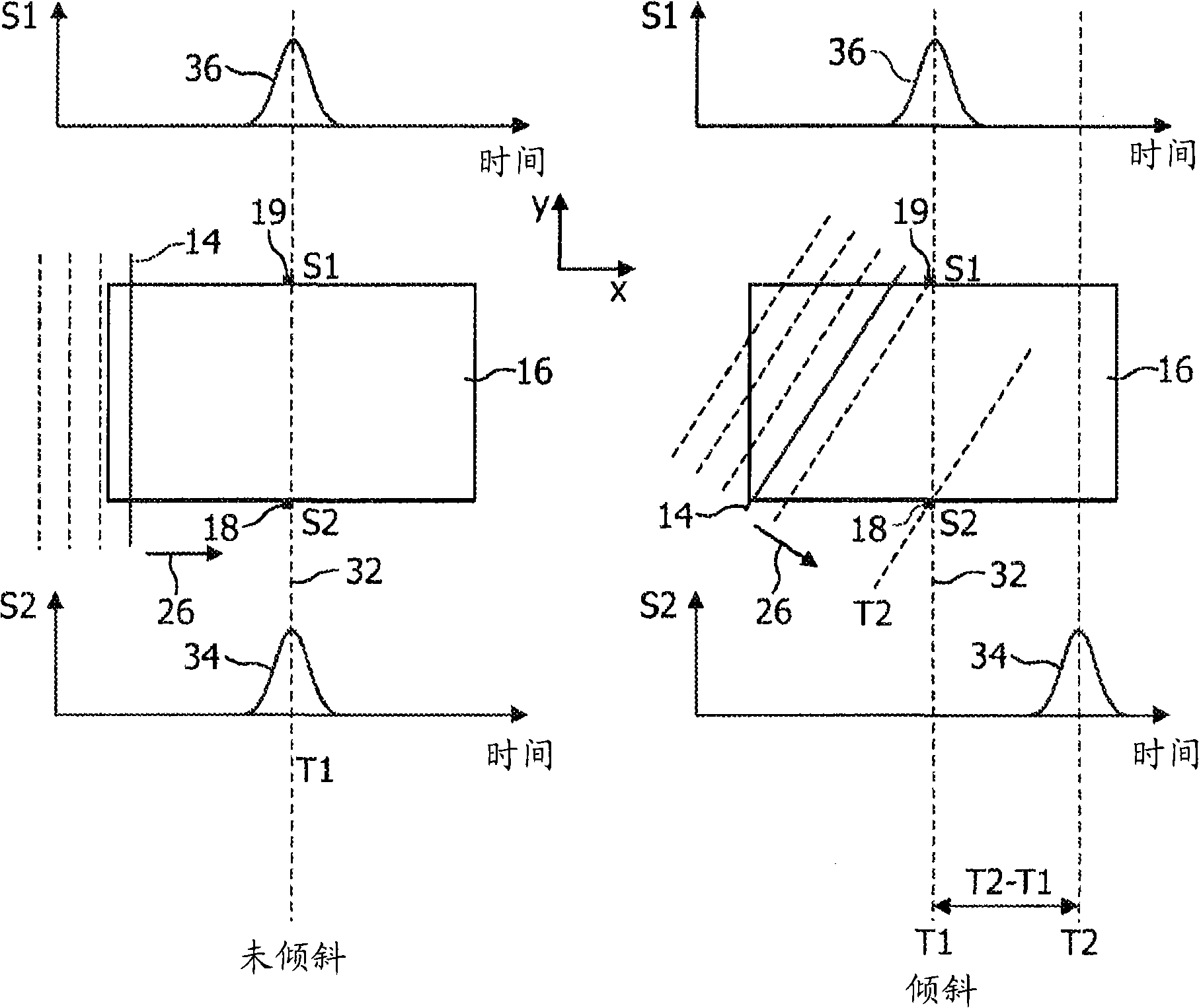
[0051] figure 1 A first embodiment of the light pen input system 10 according to the present invention is shown. The system 10 is based on the "inverse" light pen technology, and includes a light pen 12 for generating scanning light line sweeps 14 and 15 in two directions 26 and 27, which are used for detecting scanning The photodiode 18 (in the figure 1 Also marked as S2), a time measuring device 20 for measuring the duration from the start of scanning light sweeping to light detection by the photodiode 18, and a position detecting device 22 for determining the pointing position of the light pen 12 from the measured duration. The light pen input system 10 can, for example, control a cursor of a graphical user interface (GUI) shown on a display screen 16 (for example, a computer or TV display screen).

[0052] The light pen 12 generates two orthogonally arranged scanning ...


PUM


Abstract

The invention relates to a light pen input system with a light pen which is adapted to generate at least one scanning light line sweep for scanning a surface such as for example a display screen. The time from starting a scan until a light sensing element placed at a known position detects a scanning light line is measured and processed for determining the coordinates of the pointing position of the light pen. Thus, an ''inverse'' light pen is provided which may be implemented at low costs and which may be used with non-CRT displays. Furthermore, the system is independent of the display screen size.

Description

Invention field [0001] The invention relates to a light pen user interface technology that can be used in combination with a large-area non-CRT display. Background technique [0002] A conventional light pen is an input device that includes a light sensor for detecting light emitted from a cathode ray tube (CRT) display. Today's light pen technology is mainly used as an input device, such as a gun, in a game business establishment. The light pen is connected to the computer by a wire, for example, and includes a switch for causing an action to be performed by the computer, such as a switch for shooting a gun in a video game. When the computer detects the triggering of the switch, the scanning time of the electron beam in the CRT display tube from the starting point of the electron beam on the screen to the light sensor detecting the light is measured. Since the "path" of the electron beam on the screen and the coordinates of its starting point are known, the horizontal and vertic...

Claims


Application Information

Patent Timeline
IPC IPC(8): G06F3/03G06F3/042G06F3/033G06F3/0354G06F3/038
CPCG06F3/0304G06F3/03542G06F3/0386G06F3/0412G06F3/042
Inventor O·H·威廉森V·P·布伊尔M·P·C·M·克里恩G·J·德斯图拉
Owner KONINKLIJKE PHILIPS ELECTRONICS NV
Why Eureka
Try Eureka