Equipment for mixing catalyst

A technology of mixing equipment and catalyst, which is used in the field of fluidized catalytic cracking of hydrocarbon raw materials, can solve the problems of complex structure, inability to mix catalysts uniformly, and large repression effect, and achieves the effect of no pressure fluctuation, stable operation, and elimination of repression effect.

Active Publication Date: 2008-12-17
LUOYANG PETROCHEMICAL ENG CORP SINOPEC
View PDF2 Cites 14 Cited by
  • Summary
  • Abstract
  • Description
  • Claims
  • Application Information

AI Technical Summary

Problems solved by technology

[0005] The purpose of the present invention is to provide a catalyst mixing device to solve the problem that the above-mentioned lifting media existing in the existing catalyst mixing device have a relatively large blocking effect on the feeding of the feeding inclined tube and cannot well combine multiple strands of different properties. The catalysts are evenly mixed, and the structure is relatively complex, etc.

Method used


Image

  • Equipment for mixing catalyst
  • Equipment for mixing catalyst
  • Equipment for mixing catalyst

Examples


Embodiment Construction

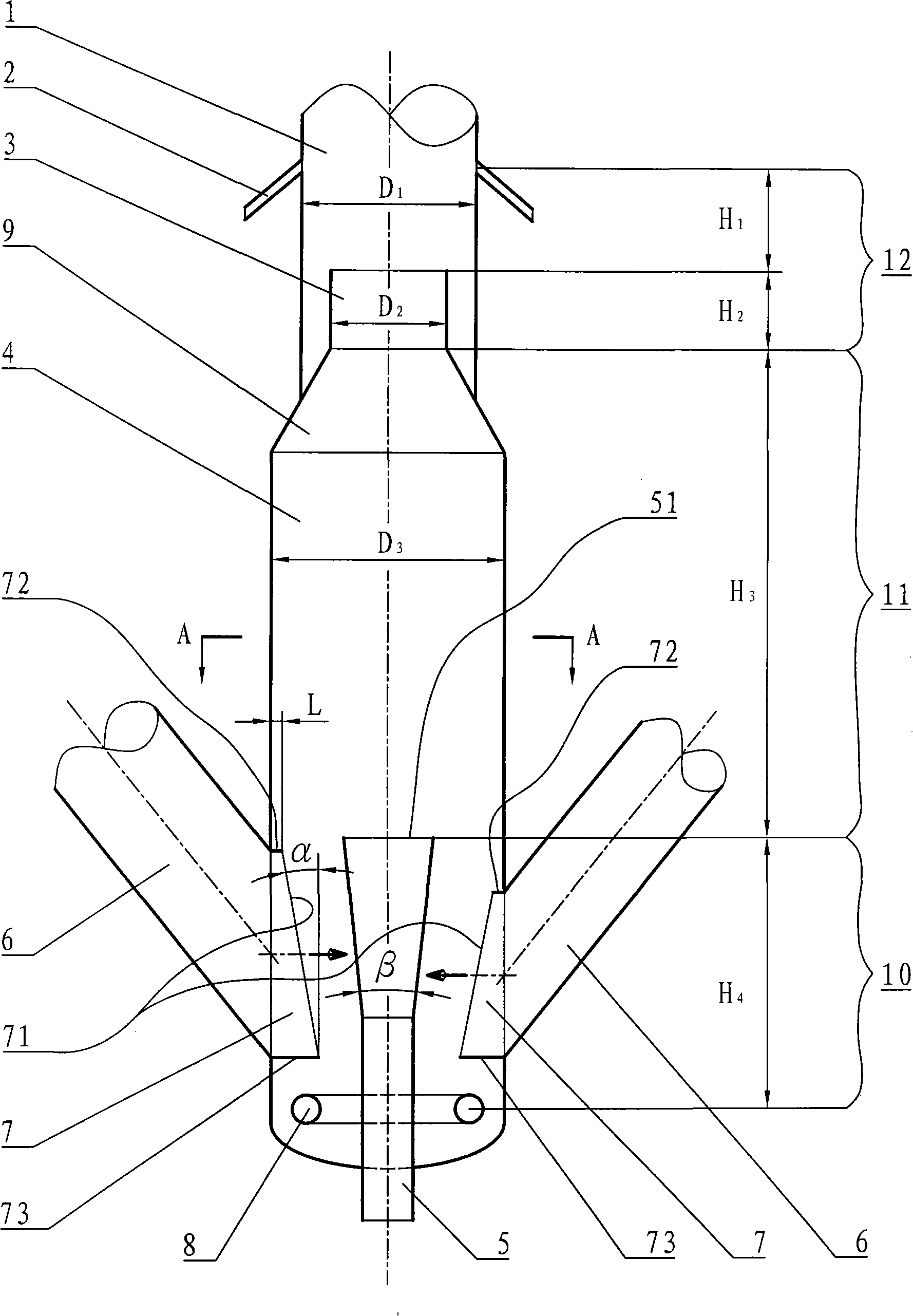
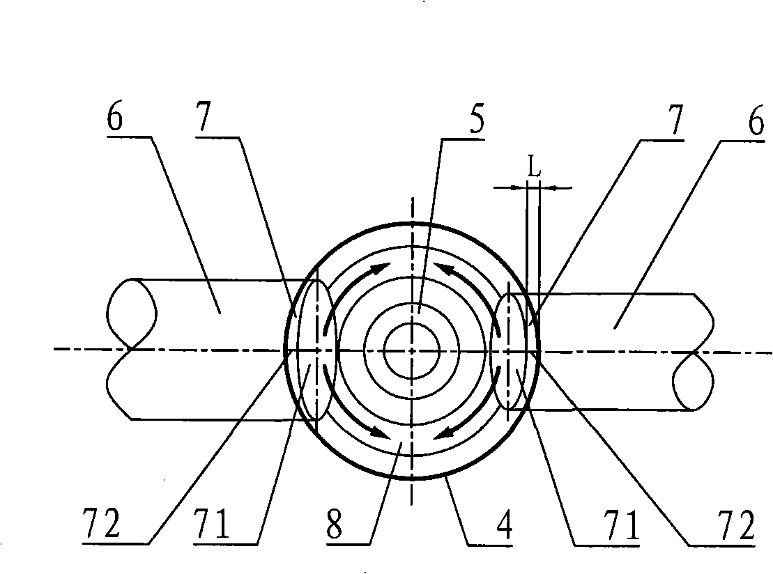
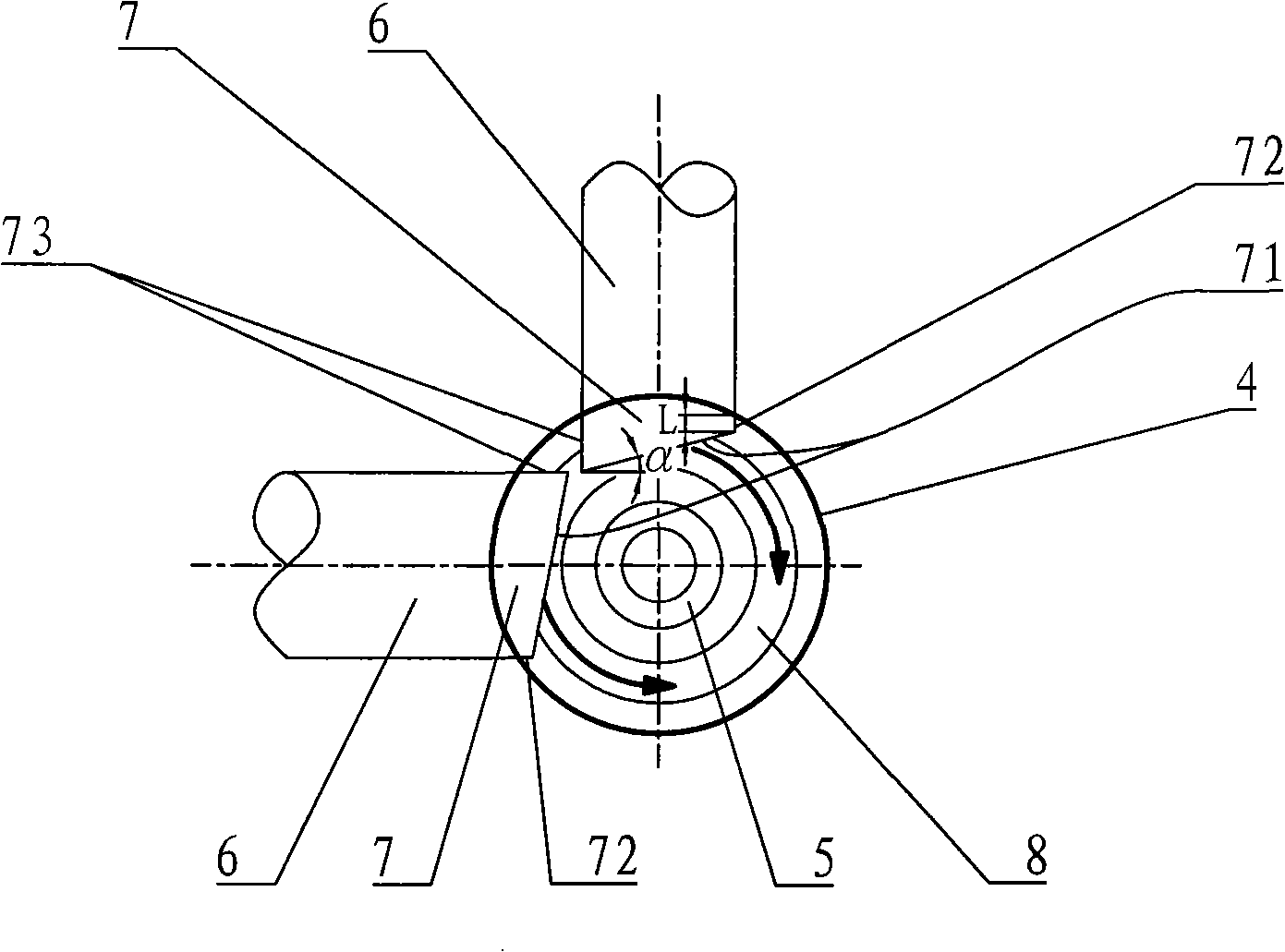
[0017] see figure 1 , figure 2 A catalyst mixing apparatus of the present invention is shown. The catalyst mixing device comprises a cylindrical barrel 4 . The top of the cylinder body 4 is provided with a conical section 9, and the bottom is provided with a head; the head is usually a hemispherical head. The conical section 9 is in the shape of a truncated conical tube and is connected to the bottom of the riser reactor 1 . There are at least two feeding inclined pipes 6 connected to the lower part of the cylinder body 4 . The inclined feeding pipes 6 are arranged around the circumferential direction of the cylinder body 4, and the number thereof is the same as the number of strands of catalysts with different properties to be mixed, the most common being two or three; figure 1 , figure 2 The catalyst mixing device shown is connected to two discharge ramps 6 .

[0018]A draft tube 7 is arranged horizontally at the interface between each feeding inclined tube 6 and the...


PUM


Abstract

The invention discloses a catalyst mixing device, aiming at solving the problems of large depression generated by a lifting medium to the blanking of an inclined blanking tube and being incapable of better uniformly mixing strands of catalysts with different characters respectively existing in the prior catalyst mixing device. In the invention, the interface locations of each inclined blanking tube (6) and each cylinder (4) is horizontally provided with a draft tube (7); the outlet end (71) of the draft tube is oblique with a plane vertical to the coaxial direction of the draft tube. A lifting medium distributer (5) is arranged in the cylinder; the top outlet (51) of the lifting medium distributer (5) is not lower than the top end of the outlet end of each draft tube. The top part of the top taper section (9) of the cylinder is provided with a deflection cylinder (3). The outlet end of the draft tube can lead the catalyst to cover an annular area between the cylinder and the lifting medium distributer on a horizontal direction after flowing out from the draft tube by surrounding the incline direction of the axial lead of the draft tube. The invention is mainly applied to a lifting tube reactor in the fluid catalytic cracking field of the hydrocarbon materials in petroleum refining and petroleum chemical industries.

Description

technical field [0001] The invention belongs to the field of fluidized catalytic cracking of hydrocarbon raw materials in petroleum refining and petrochemical industries, and relates to a catalyst mixing device used in a riser reactor. Background technique [0002] In certain types of fluidized catalytic cracking (FCC) riser reactors (such as the heavy oil riser reactor in the double riser catalytic cracking unit disclosed by Chinese patent CN100338185C), it is necessary to combine multiple strands with different properties (mainly different temperatures) Catalysts with different activities) are sent to the catalyst mixing equipment for mixing, and then the mixed catalyst enters the riser reactor, and after contacting with the feed oil mist sprayed from the feed oil nozzle on the riser reactor, the catalytic cracking reaction takes place. The purpose of mixing the catalyst is mainly to enable the riser reactor to operate under the optimized process conditions of large agent-...

Claims


Application Information

Patent Timeline
Patent Type & Authority Applications(China)
IPC IPC(8): B01F5/00C10G11/18
Inventor 张振千李国智张立新雷世远刘昱田耕乔立功
Owner LUOYANG PETROCHEMICAL ENG CORP SINOPEC
Why Eureka
Try Eureka