Mechanism for transporting mother plate in progressive die

A transmission mechanism and master mold technology, applied in metal processing equipment, forming tools, manufacturing tools, etc., can solve the problems of unsuitable micro parts, insufficient rigidity, high processing accuracy requirements, etc., and achieve the effect of convenient installation and testing, and easy part production

Active Publication Date: 2012-05-30
METAL INDS RES & DEV CENT
View PDF0 Cites 0 Cited by
  • Summary
  • Abstract
  • Description
  • Claims
  • Application Information

AI Technical Summary

Problems solved by technology

[0002] When stamping parts are processed by continuous die, the semi-finished product in processing must be transferred to the next processing station for another processing after completing a processing procedure at one processing station. The belt is connected with the belt, and the semi-finished product is transported to the next processing station by the automatic feeder pulling the material belt. Another commonly used technology is to directly pinch the semi-finished product from one processing station to the next with a pinch-type transmission mechanism. Processing station, however, in the face of the processing of fine workpieces, due to its small size, complex geometry, high processing accuracy requirements, insufficient rigidity, and difficulty in manufacturing, the above-mentioned traction by the material belt or clamping by the clamping mechanism Methods such as these are not suitable for the processing of fine parts. All these methods are still not ideal for the transmission and processing of fine parts, but there is a need for research and improvement.

Method used


Image

  • Mechanism for transporting mother plate in progressive die
  • Mechanism for transporting mother plate in progressive die
  • Mechanism for transporting mother plate in progressive die

Examples


Embodiment Construction

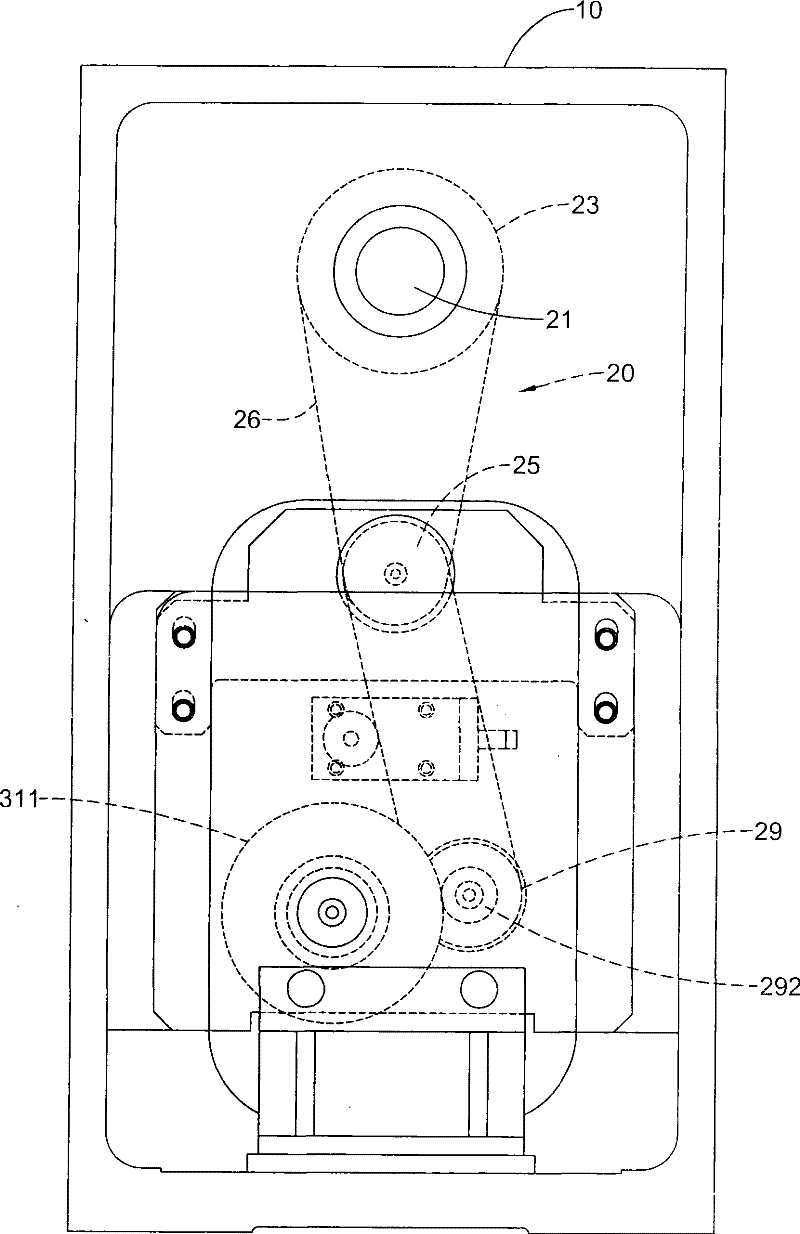
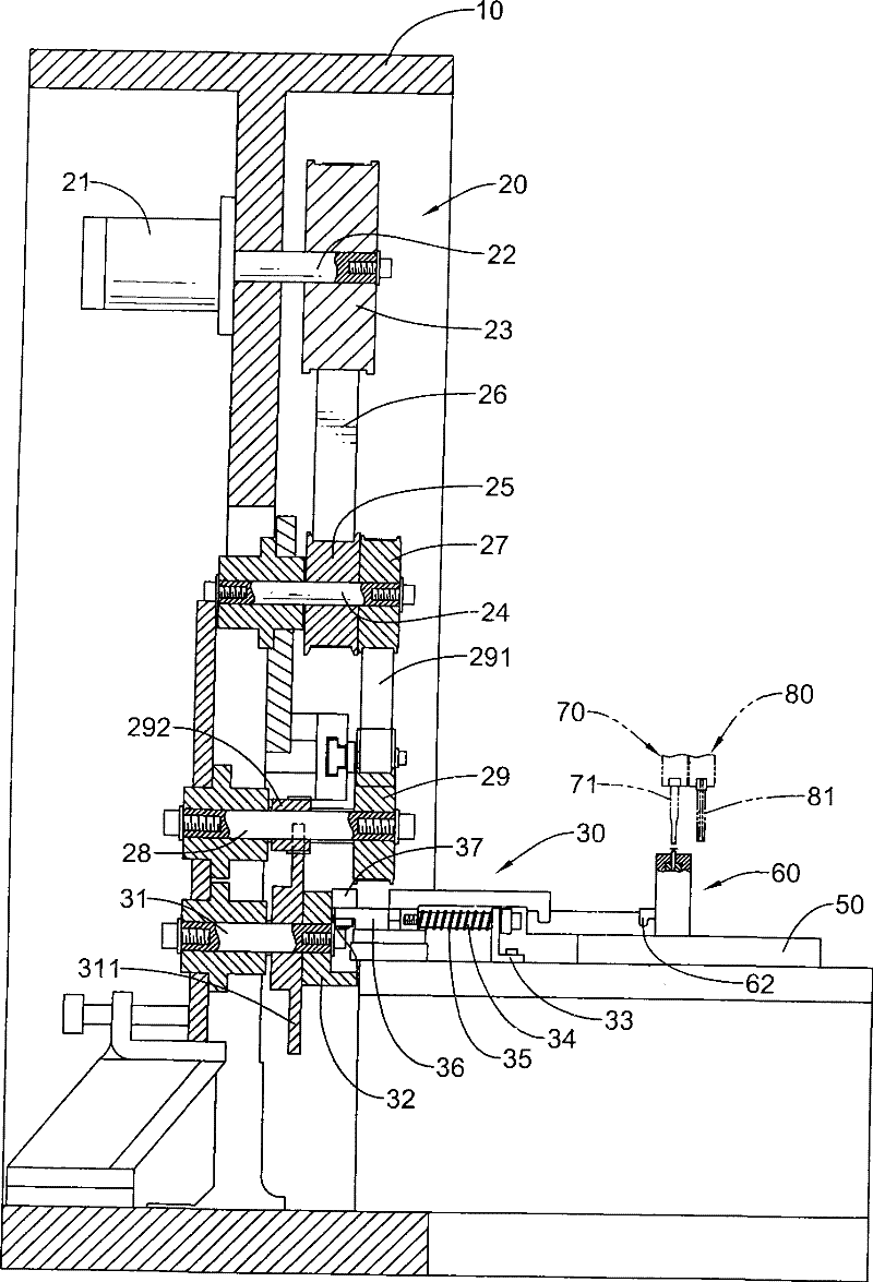
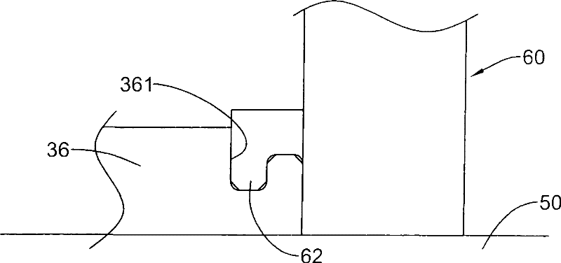
[0050] Cooperate with reference Figure 1 to Figure 3 As shown, the "continuous in-mold master mold transmission mechanism" of the present invention is to set a power device 20, a reciprocating device 30, a slide rail 50 and a master mold 60 in a machine table 10, and the master mold 60 is located at On the slide rail 50, the operation of the power unit 20 can drive the reciprocating device 30 and then drive the mother die 60 to move back and forth, and an array of punching die devices 70, 80 are arranged above the master die 60, and the front and rear movement of the master die 60 can be located at any die device 70 , 80 below for stamping work.

[0051] The power unit 20 has a motor 20, a first runner 23 is set on the output shaft 22 of the power of the motor 20, a first mandrel 24 is pivotally set on the machine table 10, and a first mandrel 24 is set on the first mandrel 24. Two runners 25 and the third runner 27, the first runner 23 and the second runner 25 are connected...


PUM


Abstract

The invention relates to a case mold delivery mechanism in a continuous mold. A power plant, a cam, a slide rail and a follower are arranged in a platform, wherein, the follower is connected with the case mold; the case mold is arranged on a slide rail; the rotation of a power plant is capable of driving the cam to rotate, and the rotation of the cam is capable of driving the follower to move thecase mold forward or backward; a plurality of sets punch die devices are arranged above the case mold; the case mold can be moved to below any punch die device for carrying out the punching operations. Through the design, the invention can replace a clamping transfer in the prior art, thus improving stability and accuracy of the production.

Description

technical field [0001] The invention relates to a transmission mechanism for a master mold in a continuous mold. Background technique [0002] When stamping parts are processed by continuous die, the semi-finished product in processing must be transferred to the next processing station for another processing after completing a processing procedure at one processing station. The belt is connected with the belt, and the semi-finished product is transported to the next processing station by the automatic feeder pulling the material belt. Another commonly used technology is to directly pinch the semi-finished product from one processing station to the next with a pinch-type transmission mechanism. Processing station, however, in the face of the processing of fine workpieces, due to its small size, complex geometry, high processing accuracy requirements, insufficient rigidity, and difficulty in manufacturing, the above-mentioned traction by the material belt or clamping by the cl...

Claims


Application Information

Patent Timeline
Patent Type & Authority Patents(China)
IPC IPC(8): B21D37/14B21D37/12B21D22/02
Inventor 杜国印蔡行知蔡添吉
Owner METAL INDS RES & DEV CENT
Why Eureka
Try Eureka