

Multipurpose clamp
A multi-purpose, fixture technology, applied in the direction of manufacturing tools, appliances for tensioning wires, and parts of bundling machinery
- Summary
- Abstract
- Description
- Claims
- Application Information
AI Technical Summary
Problems solved by technology
Method used
Image

Examples
Embodiment Construction
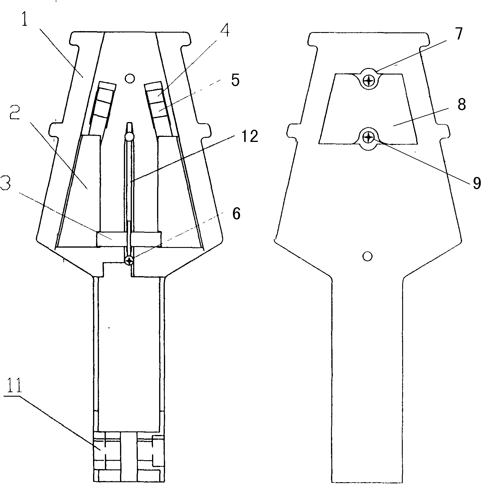
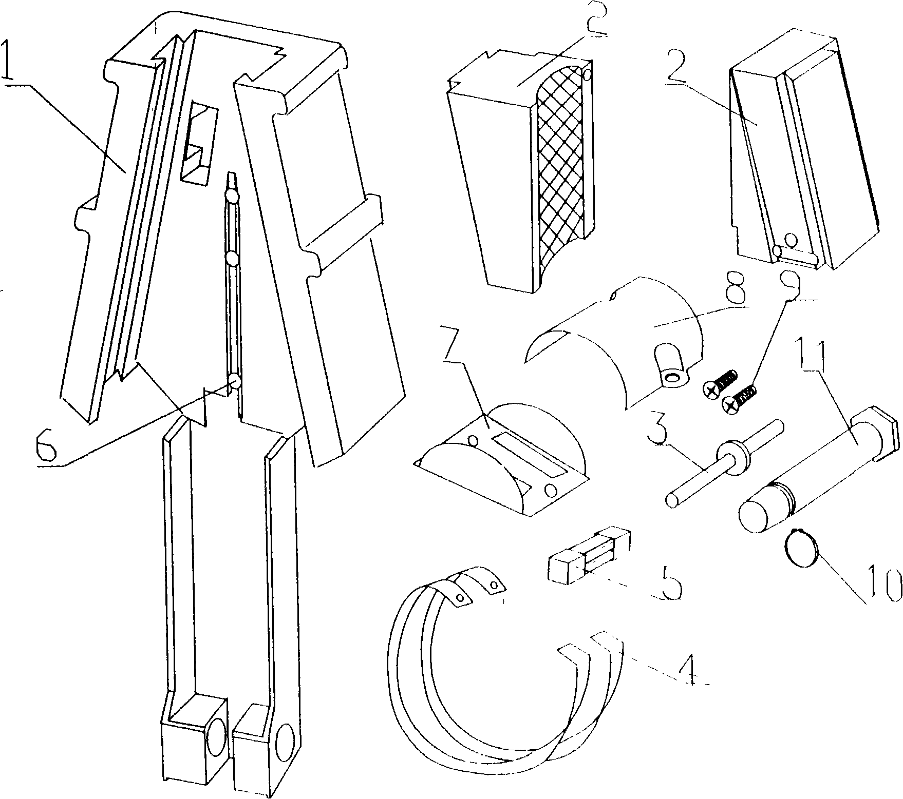
[0005] Referring to Fig. 1 and Fig. 2, a multi-purpose fixture is provided with chuck 1 main body and 2 clamping blocks, one on the left and one on the left and right, and the two 2 clamping blocks achieve consistent motion through 2 synchronizing pins. Two 2 clamping blocks can slide downwards above the 1 chuck main body, and 3 synchronous pins slide in the 12 positioning grooves on the 1 chuck main body, so that the 2 clamping blocks will not go astray. There are 6 positioning screws at the lower end of the 12 positioning slots to ensure that the 3 synchronizing pins will not slip out. The sliding of the 2 clamp block will automatically return to the upper part of the main body of the 1 chuck through the tension of the 4 extension spring, so as to tighten the rope, wire and other objects. The 4 extension spring is positioned and fixed on the back of the 1 chuck by the 5 extension spring. The extension spring pressing piece is fixed, and the 4 extension springs are protected ...
PUM
 Abstract
Description
Claims
Application Information