Manufacture method of probe short circuit preventing structure

A technology of probe short circuit and manufacturing method, which is applied to parts, instruments, and measuring devices of electrical measuring instruments, and can solve problems such as complex structure of probes and inability of probes to contact measuring contacts

Inactive Publication Date: 2011-03-30
MPI CORP
View PDF0 Cites 1 Cited by
  • Summary
  • Abstract
  • Description
  • Claims
  • Application Information

AI Technical Summary

Problems solved by technology

[0008] The purpose of the present invention is to provide a solution to the problem that the existing parallel probes with isolation design cannot touch the measurement contacts because the probes are restricted by a fixed isolation block, and the probe with isolation arms has a complex structure. problem, and the problem that the parallel-type high-density probe array cannot avoid the lateral short circuit of the parallel isolation layer, the present invention is a probe short circuit prevention structure, which is a non-conductive bulk material, and each isolation structure is fixedly embedded in the A probe body, the width of which is slightly larger than the width of the free end of each probe, and the width direction of each isolation structure protrudes toward each adjacent probe, and is not fixedly connected to the adjacent probe

Method used


Image

  • Manufacture method of probe short circuit preventing structure
  • Manufacture method of probe short circuit preventing structure
  • Manufacture method of probe short circuit preventing structure

Examples


Embodiment Construction

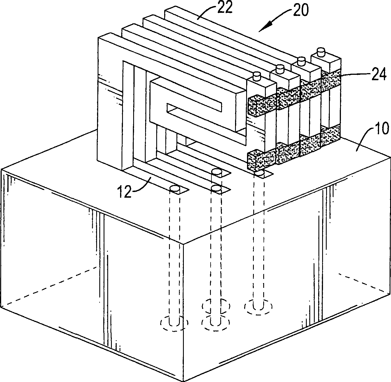
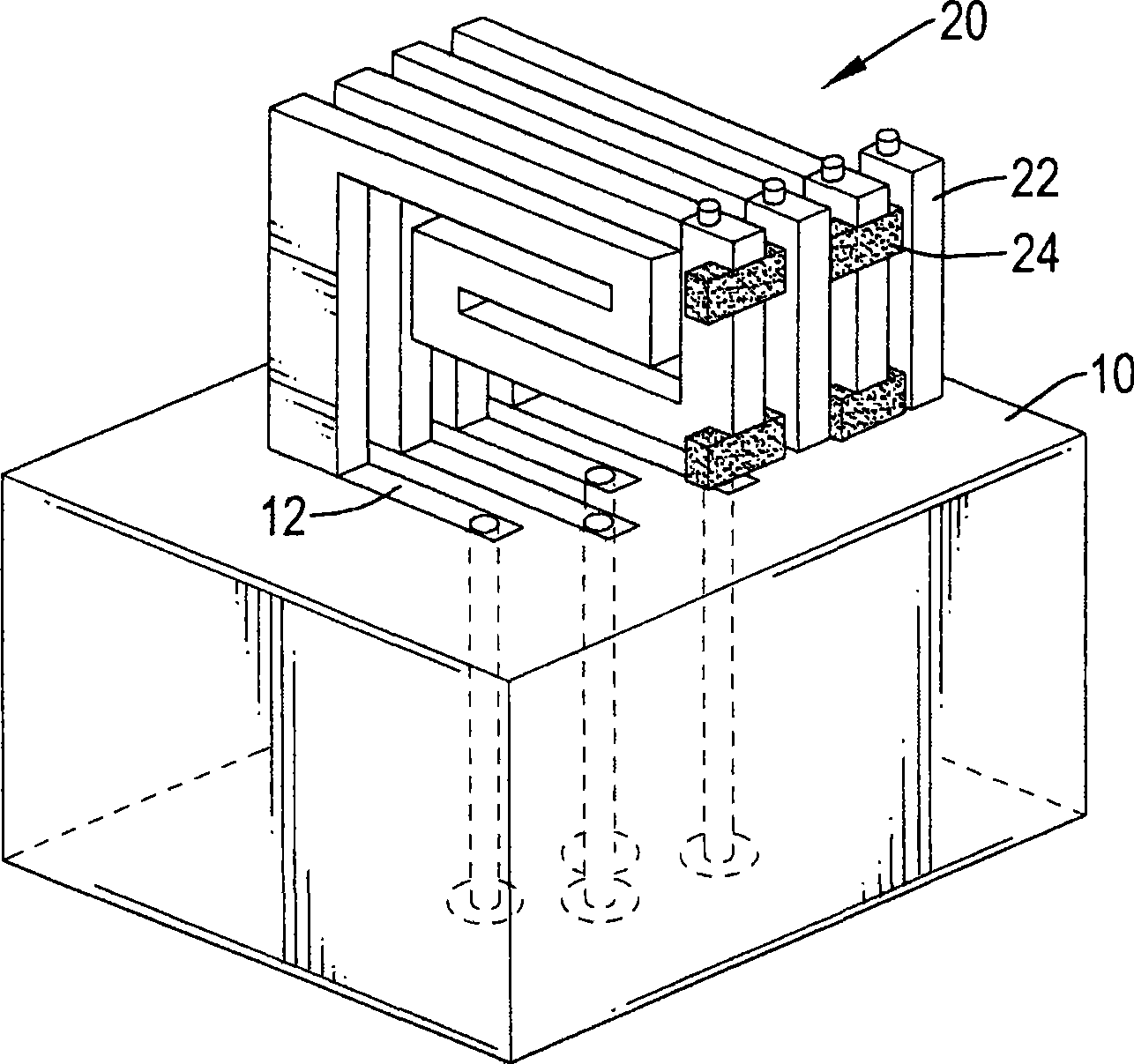
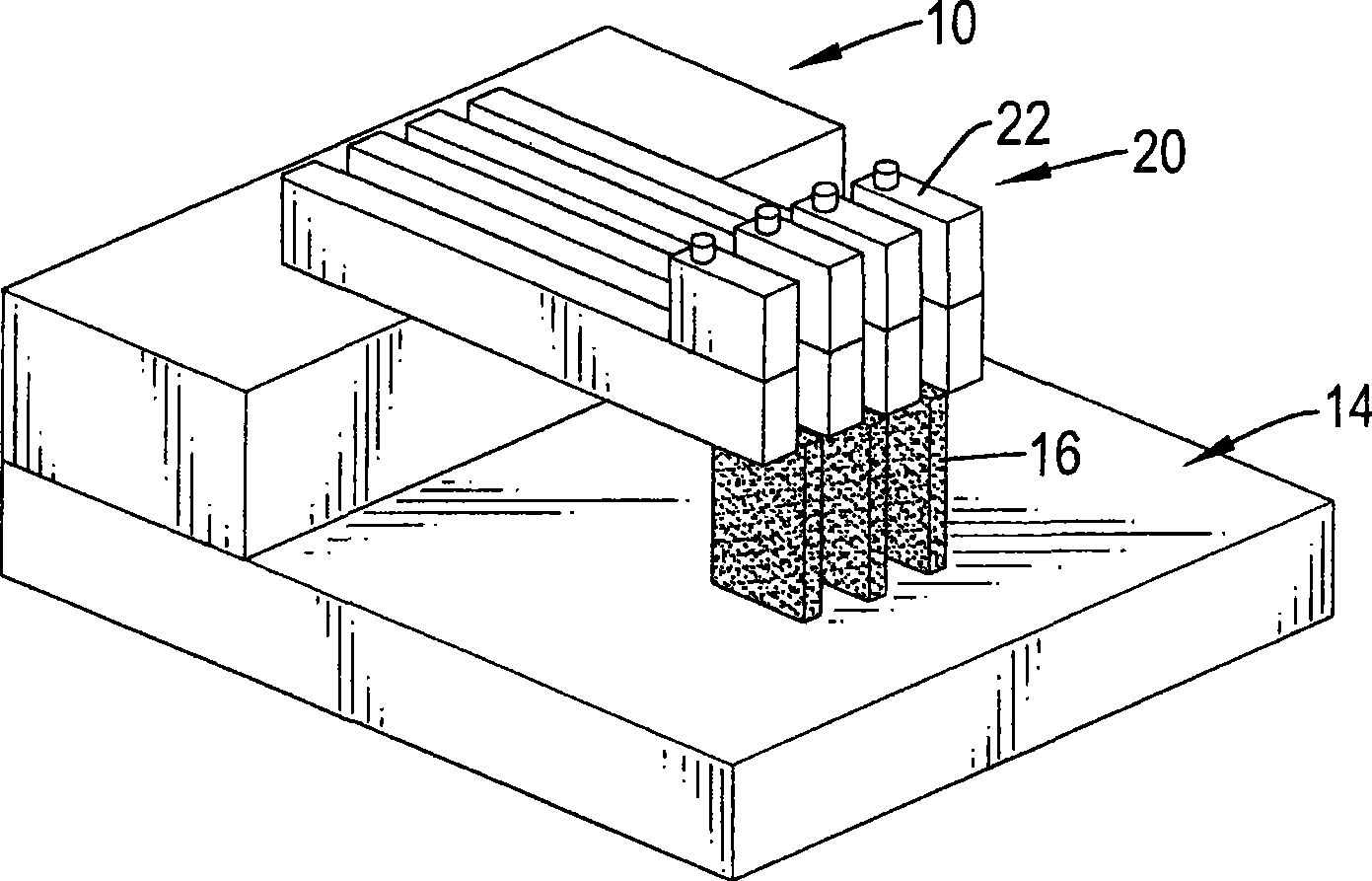
[0058] Please refer to figure 1 , is a first preferred embodiment of a probe short circuit prevention structure of the present invention, which includes a probe base 10 and a probe array 20, wherein the probe array 20 includes a plurality of probes 22 and a plurality of isolation Block 24.

[0059] The probe base 10 includes a plurality of conductive parts 12, each conductive part 12 is isolated from each other, and can be used as a contact point for connecting external signal lines (not shown in the figure).

[0060] The plurality of probes 22 have electrical conductivity and elastic deformation capability, and can be shaped into any shape, such as L-shape, long rod shape, etc. Taking this preferred embodiment as an example, the length direction has multiple bent L-shape , each probe 22 includes a cantilever portion and a contact portion, and the contact portion of each probe 22 is electrically connected and fixed to a conductive portion 12, and the cantilever portion of ea...


PUM


Abstract

The invention provides a method for manufacturing a probe short-circuit prevention structure which is an insulated separation structure; each separation structure can be embedded in a probe body or a corresponding position of a probe seat, which is at the interval of the probes, thus causing each probe to have the efficacy of mutual separation when in use.

Description

technical field [0001] The invention relates to a short-circuit preventing structure, in particular to a short-circuit preventing structure for parallel probes. Background technique [0002] Existing detection probes are often used for component performance testing of wafer chips during the packaging and testing stage. In order to achieve the purpose of shortening the test time, packaging and testing manufacturers often use parallel test probes to reduce the testing time. The so-called parallel probes are formed by arranging a plurality of detection probes in parallel; and since the distances between the measurement contacts of the chip are quite close, the distances between the detection probes must also be quite close. Generally speaking, when the parallel probes are used for chip performance testing, the parallel probes are vertically or slightly inclined to contact the corresponding measurement contacts of the probes for measurement. [0003] However, since the distance...

Claims


Application Information

Patent Timeline
Patent Type & Authority Patents(China)
IPC IPC(8): G01R1/067
Inventor 陈志忠
Owner MPI CORP
Why Eureka
Try Eureka