Method of forming piezo driver electrodes

A technology of piezoelectric transducers and electrodes, applied in ink, printing, household appliances, etc., to achieve the effect of eliminating short circuits

Active Publication Date: 2017-10-31
XEROX CORP
View PDF10 Cites 2 Cited by
  • Summary
  • Abstract
  • Description
  • Claims
  • Application Information

AI Technical Summary

Problems solved by technology

Additional challenges of the overlay coating process arise when manufacturing piezoelectric transducers by using a thick film process: a thick film process is a process that does not start with a plate, the piezoelectric material is stenciled or printed onto the substrate, as a separate patch

Method used


Image

  • Method of forming piezo driver electrodes
  • Method of forming piezo driver electrodes
  • Method of forming piezo driver electrodes

Examples


Embodiment Construction

[0032] The present embodiments will now be set forth in detail, examples of which are illustrated in the accompanying drawings. Wherever possible, the same reference numbers will be used in the drawings to refer to the same or like parts.

[0033]Notwithstanding that the numerical ranges and parameters setting forth the broad scope of the embodiments are approximations, the numerical values ​​set forth in the specific examples are reported as precisely as possible. Any numerical value, however, inherently contain certain errors necessarily resulting from the standard deviation found in their respective testing measurements. Moreover, all ranges disclosed herein are to be understood to encompass any and all subranges subsumed therein. For example, a range of "less than 10" may include any and all subranges between (and including) a minimum value of zero and a maximum value of 10, i.e. having a minimum value equal to or greater than zero and a maximum value equal to or less tha...


PUM

PropertyMeasurementUnit
thicknessaaaaaaaaaa
thicknessaaaaaaaaaa
surface tensionaaaaaaaaaa

Abstract

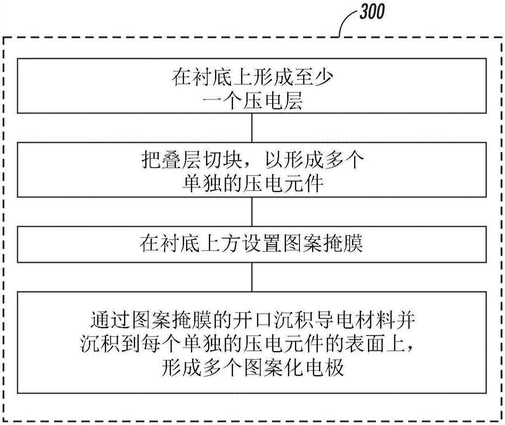
A method for forming piezoelectric transducers for inkjet printheads includes: forming at least one piezoelectric layer on a substrate; forming at least one electrode pattern by depositing a conductive material on an exposed surface of the at least one piezoelectric layer; and forming a plurality of individual piezoelectric elements from the at least one piezoelectric layer before or after the forming of the at least one electrode pattern.

Description

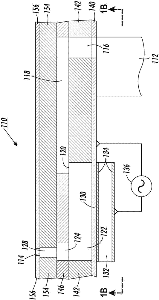
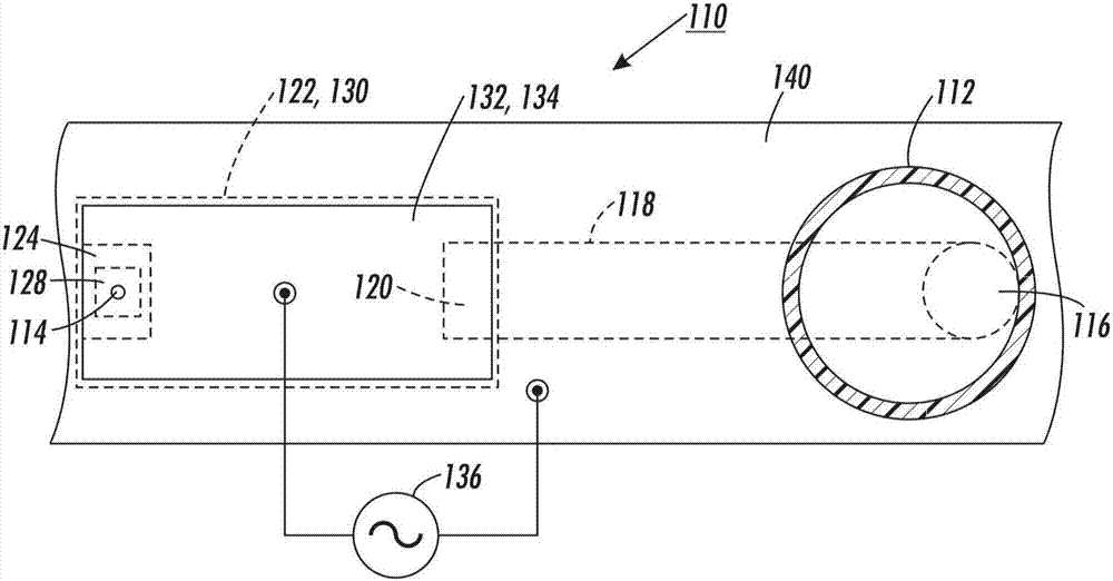
technical field [0001] Embodiments described herein relate generally to the field of printing, in particular inkjet printing, and in particular to the field of inkjet printhead component fabrication. Background technique [0002] Printing images onto print media such as paper for consumer and industrial use is generally dominated by laser technology and inkjet technology. Inkjet technology has become more common as the resolution and quality of inkjet printing has improved. Inkjet printers typically use thermal inkjet technology or piezoelectric technology. Even though piezo inkjet is more expensive to manufacture than thermal inkjet, piezo inkjet is generally favored due to its ability to use a wider variety of inks. [0003] A piezoelectric inkjet printhead includes an array of piezoelectric transducers attached to a flexible membrane. Other printhead structures may include one or more laser-patterned dielectric spacer layers and a flexible printed circuit ("flex circui...

Claims


Application Information

Patent Timeline
Patent Type & Authority Applications(China)
IPC IPC(8): B41J2/16
CPCB41J2/161B41J2/1612B41J2/1621B41J2/1623B41J2/1628B41J2/1631Y10T29/42Y10T29/49401B41J2/1632B41J2/14274B41J2/1607B41J2/1618B41J2/1635B41J2/164C09D11/30C09D11/36C09D11/52
Inventor G·D·雷丁P·J·奈斯特龙P·M·高尔文M·A·赛卢拉
Owner XEROX CORP
Why Eureka
Try Eureka