

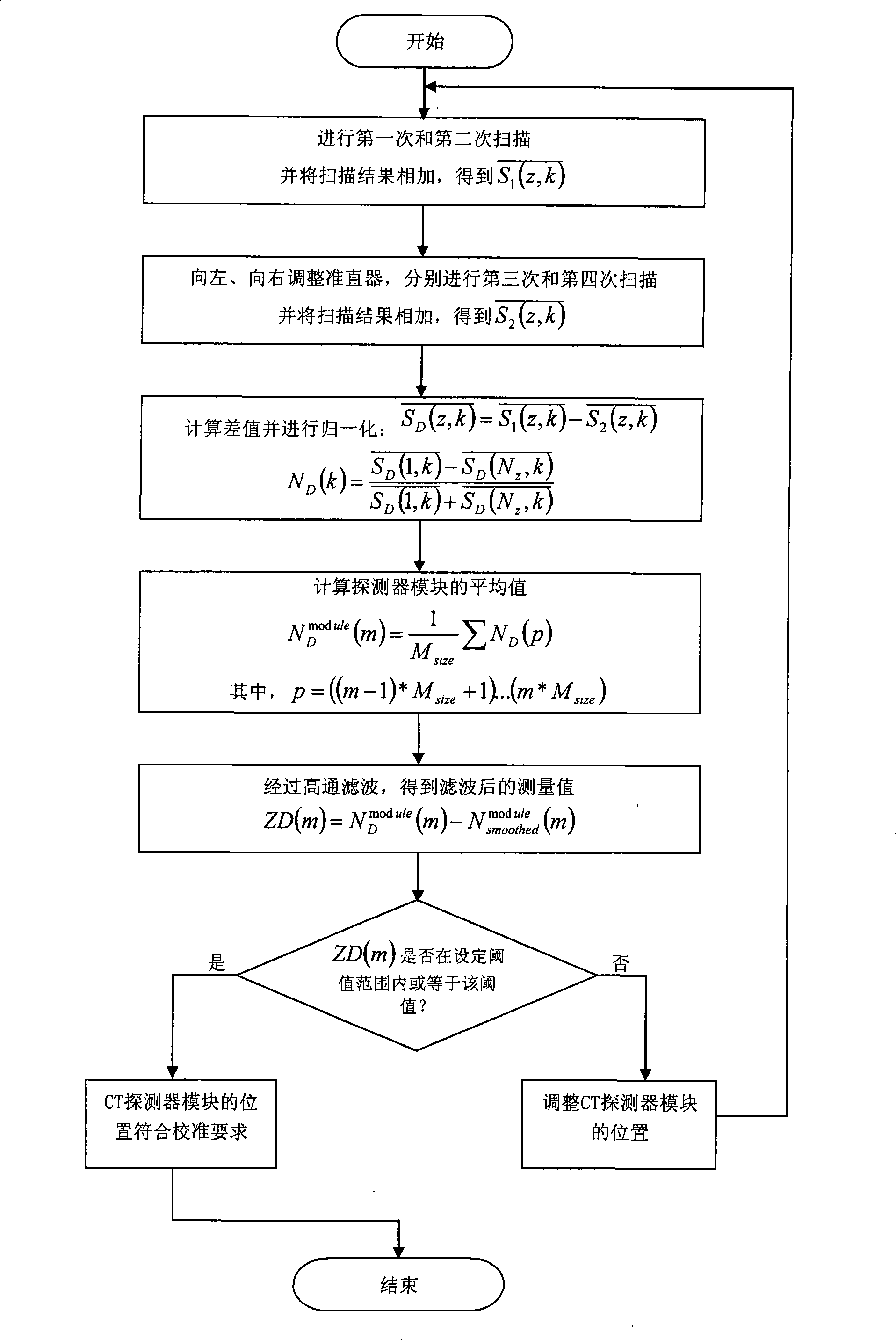
Method for calibrating and detecting CT detector module
A detector and CT scanning technology, applied in radiation intensity measurement, computerized tomography scanner, echo tomography, etc., can solve problems such as misalignment, and achieve the effect of preventing artifacts and avoiding position deviation
- Summary
- Abstract
- Description
- Claims
- Application Information
AI Technical Summary
Problems solved by technology
Method used
Image

Examples
Embodiment Construction
[0025] The present invention will be described in detail below in conjunction with the accompanying drawings.
[0026] Multi-slice spiral CT is the most popular CT equipment at present. Compared with single-slice spiral CT, the biggest difference between multi-slice spiral CT is to increase the number of detector rows in the z-axis direction to achieve the purpose of multi-slice sampling. Single-slice helical CT has a row of detectors in the z-axis direction, while multi-slice helical CT is composed of multiple rows of detectors to form a detector array, so this type of CT is also called multi-row helical CT.
[0027] A multi-row detector consists of several detector modules with the same structure. Structurally, each detector module includes several rows and several channels. The number of rows of each detector module is the number of rows of the entire CT detector, and the sum of the number of channels of all detector modules is the number of channels of the entire CT dete...
PUM
 Abstract
Description
Claims
Application Information