
Method for reverse phase detection of audio signal left and right acoustic channels

An audio signal, left and right channel technology, applied in the detection field, can solve problems such as the inability to simply specify audio inversion, the inability to visually judge the inversion problem, equipment abnormality or wiring problems, etc., to achieve excellent detection results, reduce impact, and eliminate The effect of the influence of audio randomness

Inactive Publication Date: 2008-12-24
上海风格信息技术股份有限公司 +1
View PDF0 Cites 6 Cited by
  • Summary
  • Abstract
  • Description
  • Claims
  • Application Information

AI Technical Summary

Problems solved by technology

For example, negligence when picking up sound, abnormal equipment or wiring problems in the transmission system, wrong operations during audio playback, etc. can all cause inversion problems
On the other hand, since the human ear is not sensitive to the audio phase in mono, it is impossible to intuitively judge the phase inversion problem, and a special monitoring method must be used
[0004] There is randomness in the audio phase in nature, so it is impossible to simply specify a certain threshold as a criterion for judging audio inversion

Method used


Image

  • Method for reverse phase detection of audio signal left and right acoustic channels
  • Method for reverse phase detection of audio signal left and right acoustic channels
  • Method for reverse phase detection of audio signal left and right acoustic channels

Examples


Embodiment Construction

[0035] Hardware configuration: Development board based on Intel XScale PXA-255 core.

[0036] Software configuration: GNU open source operating system: Linux-2.4 kernel; Glibc-2.2.5 runtime library; BusyBox console.

[0037] Preset parameters: detection time slice length 40ms; inversion probability 60%; detection time length 10s; inversion sensitivity 90%; inversion time threshold 2s; in-phase time threshold 2s.

[0038] Detection results: 0% false alarm rate, 0% false negative rate.

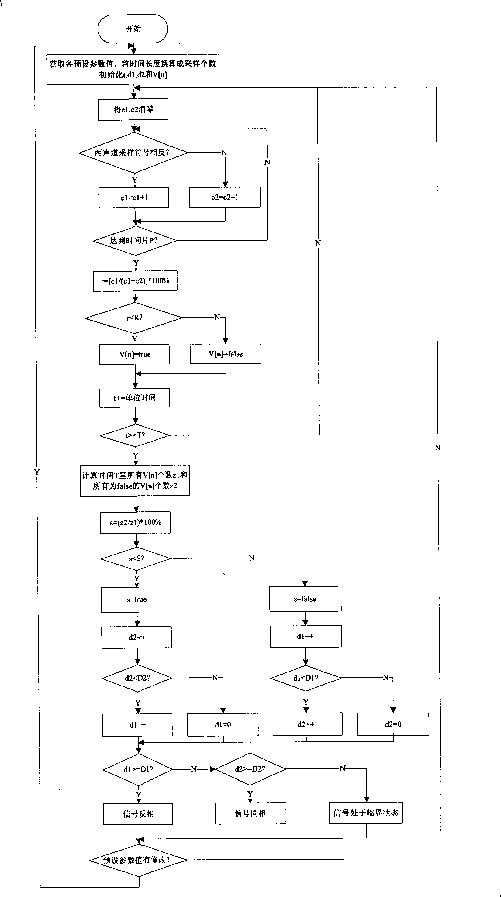
[0039] According to the accompanying drawings, when the detection method of the present invention begins, the detection parameters should be read: detection time slice P, inversion probability threshold R, detection time length T, inversion sensitivity S, inversion time threshold D1 and in-phase time threshold D2 , and convert P, T, D1 and D2 into the number of samples according to the sampling rate for the following calculation needs. In addition, when the method starts, the inverted sampling...


PUM


Abstract

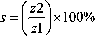
The invention relates to a left and right track reversed phase detection method for an audio signal, and is characterized in that the method comprises the following detection steps: each preset parameter value is obtained, and each intermediate variable is initialized; a sampled value is obtained by using audio collection equipment, and in a detection time slice P, the reversed phase sampling time c1 and the same phase sampling time are counted; if the reversed phase probability r is larger than a threshold R of the reversed phase probability, a current audio signal state value V(n) is judged to be a reversed phase; when the accumulated detection time t is larger than or equal to the length T of the detection time, the reversed phase percentage s is calculated; when the reversed phase percentage s is larger than the reversed phase sensitivity S, the state of the current audio signal is determined to be the reversed phase; when an accumulated reversed phase time d1 is larger than or equal to a threshold D1 of the reversed phase time, the audio signal is confirmed to be in the reversed phase; when an accumulated same phase time d2 is larger than or equal to the threshold D2 of the same phase time, the audio signal is confirmed to be in the same phase; otherwise, the audio signal is in the critical state. The detection method confirms the final state in combination with a historical state value and a current state value, thereby greatly reducing the affect of the randomness of an audio phase to the stability of a detection result, and ensuring the accuracy of the detection method; therefore, the detection method is applicable to various sound systems application situations.

Description

technical field [0001] The invention relates to a detection method, and in particular discloses a detection method for the left and right channels of an audio signal, which is applied to radio, television, recording and playback of large-scale conferences and the like. Background technique [0002] The phase inversion of the left and right channels of an audio signal refers to the situation that the phase difference between the left and right channels is close to 180°. The reverse of the left and right channels will not only seriously affect the transmission distance and quality of the signal, but also cause great damage to the sound quality of the broadcast. This is unacceptable for audio-centric applications such as media operations, company meetings, and large-scale concerts. Therefore, it is necessary to detect and locate errors in the entire system in the first place. [0003] In practical applications, there are many factors that cause the phase inversion of the left ...

Claims


Application Information

Patent Timeline
IPC IPC(8): H04S7/00H04S1/00
Inventor 顾樑王波惠新标邵勇陈立德曹毅吕家瑜肖力华
Owner 上海风格信息技术股份有限公司
Learn More