Sound emission and collection device

A sound emitting and collecting device technology, applied to frequency/direction characteristic devices, transducer acoustic response prevention, sensor components, etc., can solve problems such as easy surround microphone, loud speaker to microphone volume, heavy processing burden, etc.

Inactive Publication Date: 2008-12-24
YAMAHA CORP
View PDF2 Cites 31 Cited by
  • Summary
  • Abstract
  • Description
  • Claims
  • Application Information

AI Technical Summary

Problems solved by technology

[0005] However, in the structure of Patent Document 1, a compact structure is provided, however, the speaker and the microphone are close to each other, and the volume of the surround sound from the speaker to the microphone is large
On the other hand, in the structure of Patent Document 2, the echo canceller function suppresses the surround sound, and the elastic body suppresses the sound coupling inside the cabinet, however, the speaker and the microphone are still close to each other to form the compact structure in Patent Document 1
For this reason, there is still the problem that the sound emitted from the speaker tends to surround the microphone and imposes a heavy processing burden on the echo canceller function

Method used


Image

  • Sound emission and collection device
  • Sound emission and collection device
  • Sound emission and collection device

Examples


no. 1 example

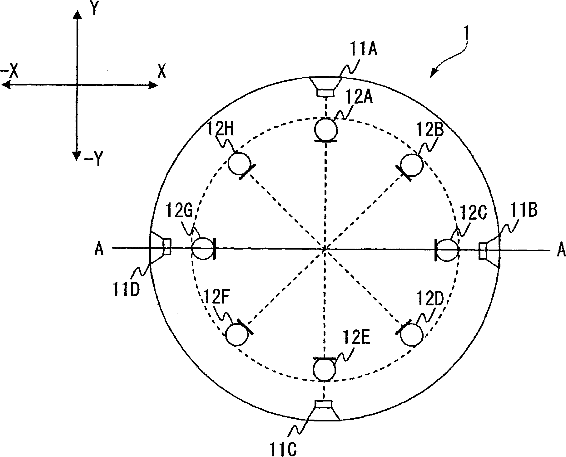
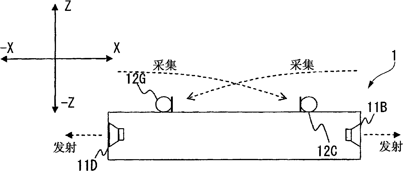
[0110] A sound emitting and collecting device according to an embodiment of the present invention will be described with reference to the accompanying drawings. figure 1 is a top view of the sound emitting and collecting device according to this embodiment, Figure 2A yes figure 1 A-A sectional view of . exist figure 1 , the right side of the paper is the X direction, the left side is the -X direction, the upper side is the Y direction, and the lower side is the -Y direction. exist Figure 2A , the right side of the paper is the X direction, the left side is the -X direction, the upper side is the Z direction, and the lower side is the -Z direction.

[0111] The sound emitting and collecting device includes a cylindrical casing 1, a plurality (four in this example) of loudspeakers 11A-11D arranged at equal intervals on the concentric circles of the outer circumference of the casing 1, and a plurality (in this example) In the example, there are eight) microphones 12A-12H (...

Embodiment 1

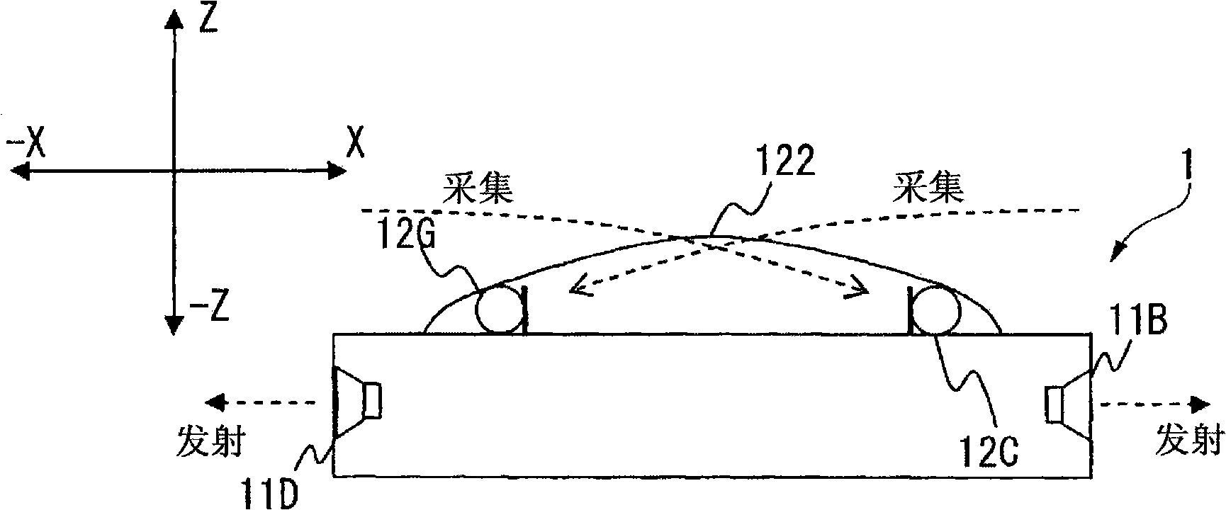
[0135] Fig. 7 shows the structure of the sound emitting and collecting device in another example. FIG. 7 is a plan view and a sectional view showing another example of a sound emitting and collecting device. Figure 7A is the top view of the sound emitting and collecting device, Figure 7B yes Figure 7A A-A cross-sectional view of the sound emitting and collecting device. exist Figure 7A , the right side of the paper is the X direction, the left side is the -X direction, the upper side is the Y direction, and the lower side is the -Y direction. exist Figure 7B , the right side of the paper is the X direction, the left side is the -X direction, the upper side is the Z direction, and the lower side is the -Z direction. and figure 1 Components that are the same as those of the sound emitting and collecting device in FIG. 2 are assigned the same reference numerals, and their descriptions are omitted.

[0136] In this example, the sound emitting and collecting device incl...

Embodiment 2

[0141] Also, the sound emitting and collecting device may have a structure as shown in FIG. 8 . Fig. 8 is a plan view and a sectional view showing another example of a sound emitting and collecting device. Figure 8A is a top view of the sound emitting and collecting device, Figure 8B yes Figure 8A A-A cross-sectional view of the same sound emitting and collecting device in . exist Figure 8A , the right side of the paper is the X direction, the left side is the -X direction, the upper side is the Y direction, and the lower side is the -Y direction. exist Figure 8B , the right side of the paper is the X direction, the left side is the -X direction, the upper side is the Z direction, and the lower side is the -Z direction. Also in this example, with figure 1 Components that are the same as those of the sound emitting and collecting device in FIG. 2 are assigned the same reference numerals, and their descriptions are omitted.

[0142] In the example of the same figure,...


PUM


Abstract

It is possible to provide a sound emission and collection device having a compact configuration and capable of suppressing sound coming from a speaker to a microphone and improving the S / N ratio. In the sound emission and collection device, a plurality of speakers (11) have a sound emission surface arranged at the side surface of a case (1) so that a sound can be emitted in all the circumferential direction of the sound emission and collection device. Each of the microphones (12) is arranged with the sound collection direction set in the center direction of the case (1). The microphone (12) and the speaker (11) have directivities opposing to each other. Accordingly, it is possible to minimize the sound coming from the speaker (11) to the microphone (12). Moreover, since the speaker (11) and the microphone (12) are arranged on coaxial circumferences, it is possible to obtain a compact configuration.

Description

technical field [0001] The present invention relates to a sound emitting and collecting device which generally includes a speaker and a microphone, and more particularly to a sound emitting and collecting device having a compact structure and capable of suppressing surround sound from the speaker to the microphone. [0002] This application claims priority based on Japanese Patent Application No. 2005-364617 filed on December 19, 2005 and Japanese Patent Application No. 2005-368052 filed on December 21, 2005, the contents of which are incorporated herein by reference. Background technique [0003] A teleconference apparatus, which integrally includes a speaker and a microphone, has been released as an audio communication system for performing an audio conference (teleconference) at a remote location. The audio conferencing device transmits the sound signal collected by the microphone to the connection terminal, and emits the sound signal received from the connection terminal...

Claims


Application Information

Patent Timeline
Patent Type & Authority Applications(China)
IPC IPC(8): H04R1/40H04R3/00H04R3/02
Inventor 石桥利晃齐藤康祐
Owner YAMAHA CORP
Why Eureka
Try Eureka