Combined harvester

A technology for combine harvesters and harvesting devices, which is applied in the directions of harvesters, cutters, agricultural machinery, etc., can solve the problems of oil cooler damage, lowering, damage and durability of pipes used for water supply, etc., and achieves easy movement, improved effect, The effect of easy maintenance

Inactive Publication Date: 2008-12-31
ISEKI & CO LTD
View PDF1 Cites 9 Cited by
  • Summary
  • Abstract
  • Description
  • Claims
  • Application Information

AI Technical Summary

Problems solved by technology

[0004] Therefore, there are problems such as damage to the oil cooler, damage to the water supply pipe, or deterioration in durability during operation.

Method used


Image

  • Combined harvester
  • Combined harvester
  • Combined harvester

Examples


Embodiment Construction

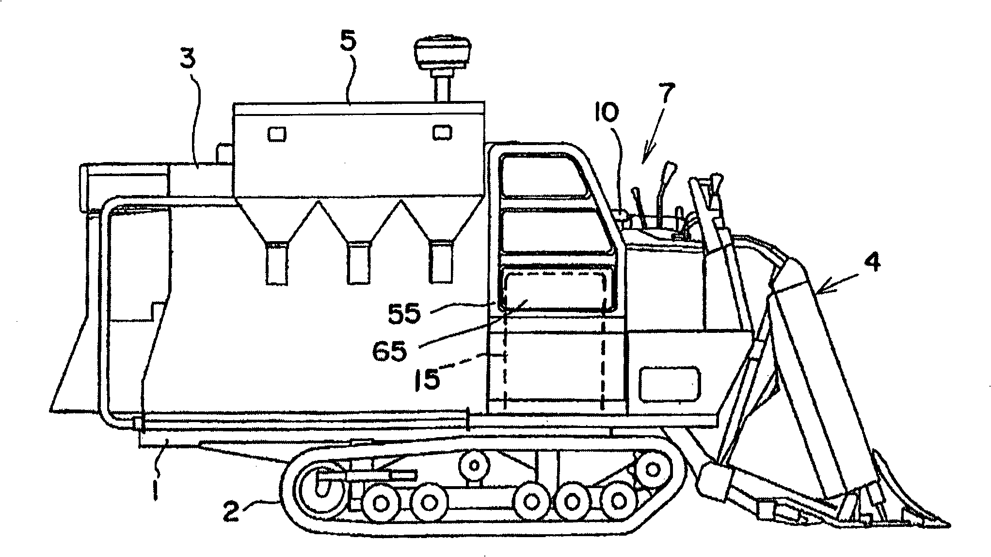
[0039] Embodiments of the present invention will be described with reference to the drawings. Such as figure 1 As shown, 1 is the frame, 2 is the traveling device arranged at the lower position of the frame 1, 3 is the threshing device arranged at the upper position of the frame 1, and 4 is the harvesting device arranged at the front side of the threshing device 3 , 5 is a hopper arranged on the right side of the threshing device 3, and 7 is a manipulation part.

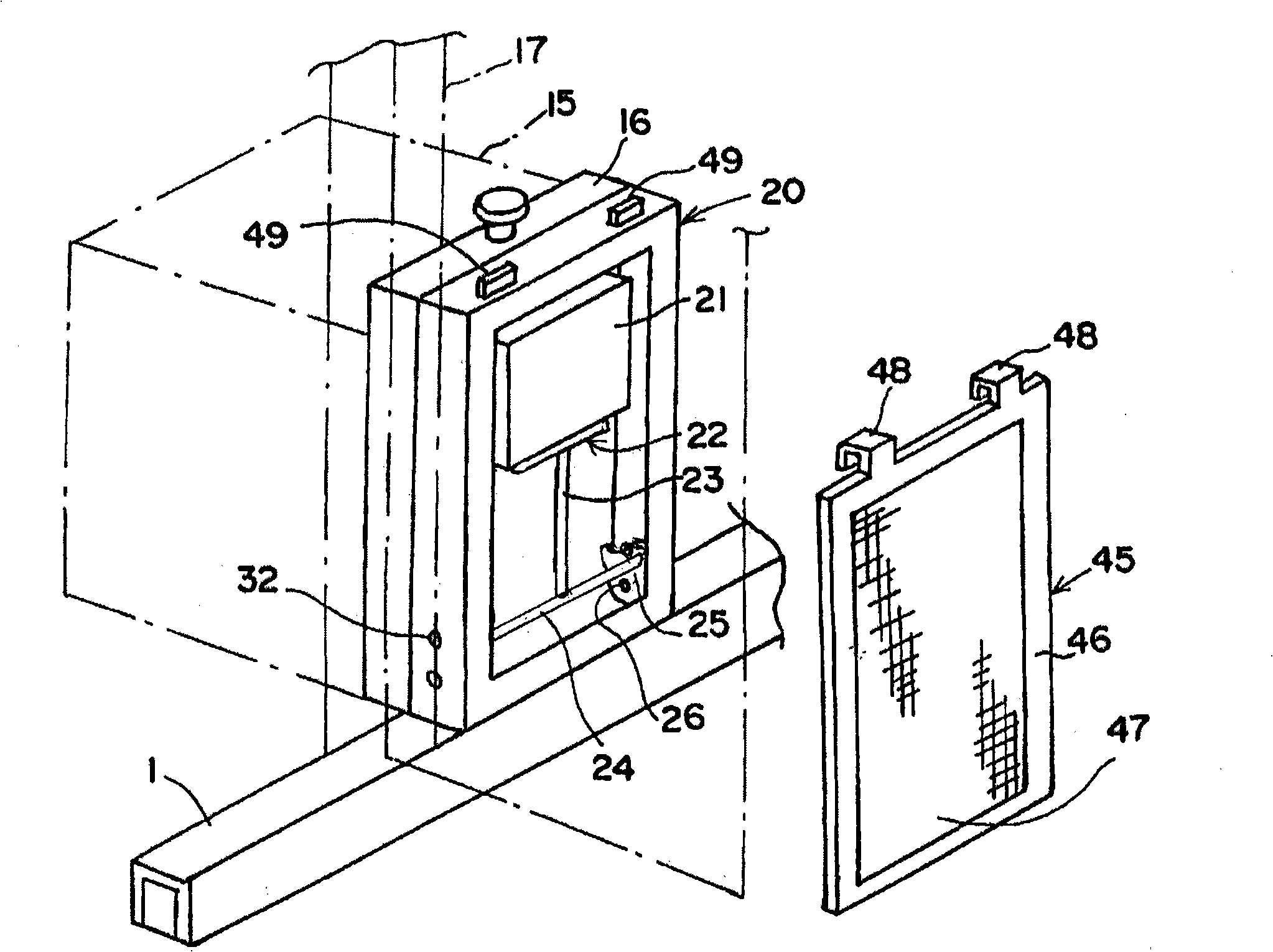
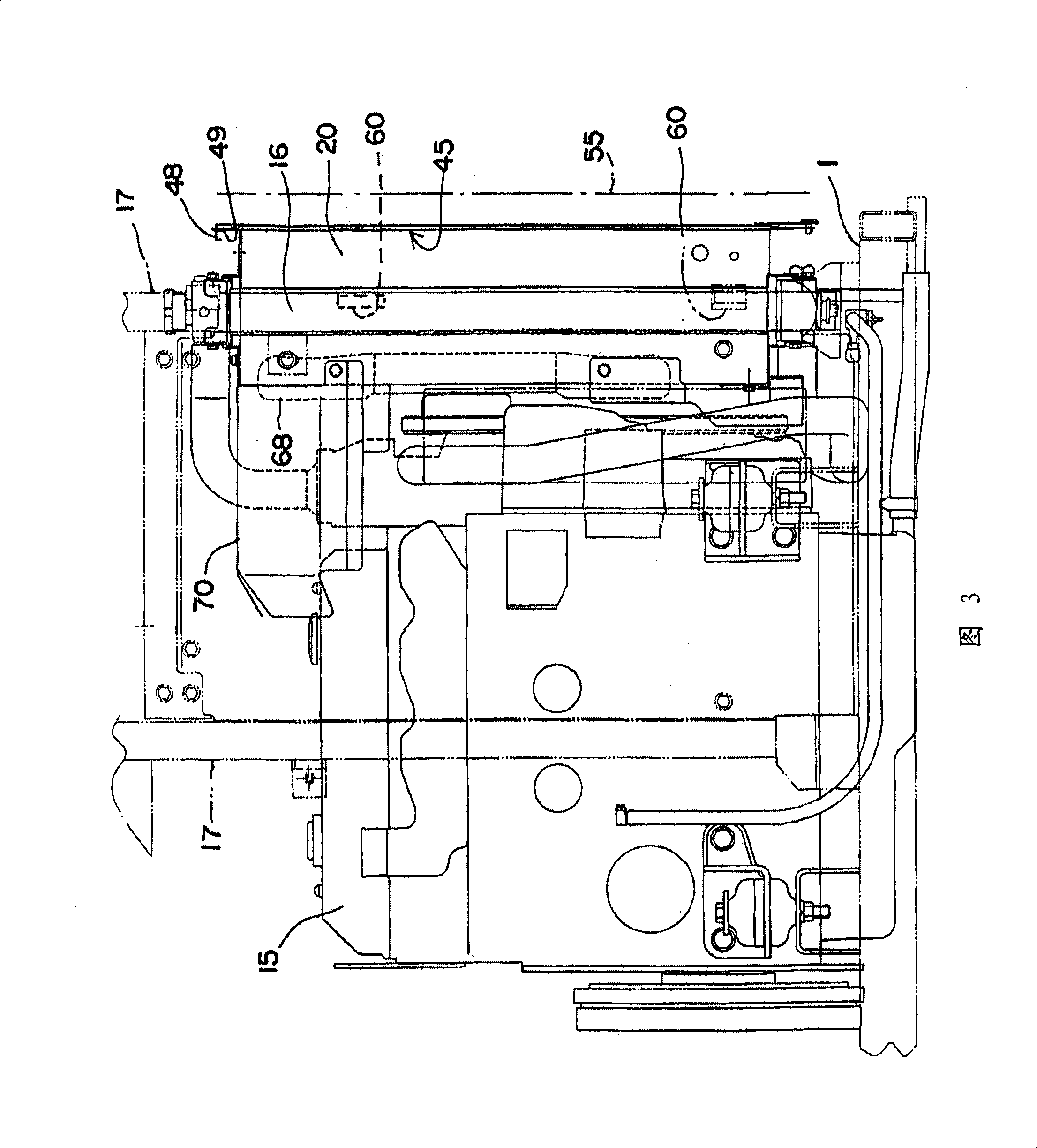
[0040] Therefore, an engine 15 is provided below the driver's seat 10 of the manipulation unit 7 . Such as figure 2 As shown, a radiator 16 is provided outside the oil outside of the engine 15 . The radiator 16 is attached in a fixed state to a vertical frame 17 fixed to the rack 1 . A frame body 20 is provided on the oil outer side of the radiator 16 . The frame body 20 is formed as a rectangular steel plate frame body having substantially the same size as the radiator 16 when viewed from the side of the body....


PUM


Abstract

The invention provides a combine-harvester capable of making it easier to maintain an oil cooler power and dustproof mesh equipped at a power section, thereby improving operation effect of the combine-harvester. According to constitution of the inventive combine-harvester, a frame body (20) is equipped at right and external side of the heat radiator (16), lower part of a mounting component (25) is freely reelingly equipped on the right and external side, a fixed rotation limiting brake (32) is equipped at concave section (33) of the upper part forming in the mounting component, end part of a transverse shaft (24) is fixed on upper part of the mounting component, lower part of the fixed support part (23) is fixed on the transverse shaft, an oil cooler (21) is fixed on upper part of the support component, the oil cooler is equipped in the frame body. A second clamp part (48) equipped on upper part of the dustproof mesh (45) and a fixing side clamp part (49) are clamped, and the dustproof mesh (45) is fixed by being pressed to the frame body with an engine hood (55).

Description

technical field [0001] The present invention relates to combine harvesters. Background technique [0002] A radiator is arranged on the outside of the engine, an oil cooler is arranged on the outside of the radiator, and the configuration that the oil cooler is detachably mounted on the radiator is a known technology (patent document 1: Japanese Patent Application No. Bulletin). [0003] Since the oil cooler of the above known example is detachably attached to the radiator, the oil cooler can be removed for maintenance of the radiator. But this is nothing more than dismantling the oil cooler. Actually, the water supply pipe is supported on the dismantled oil cooler while still hanging. [0004] Therefore, there are problems such as damage to the oil cooler, damage to the water-feeding pipe, or deterioration in durability during operation. Contents of the invention [0005] The invention facilitates the movement of the oil cooler and the overall maintenance work of the r...

Claims


Application Information

Patent Timeline
Patent Type & Authority Applications(China)
IPC IPC(8): A01D41/02A01D41/12A01B71/08
Inventor 山本昌一长井敏郎白方干也西辻雅树上加郁朗川口弘道
Owner ISEKI & CO LTD
Why Eureka
Try Eureka