Adjustable blade pitch device eccentric lining structure and assembly method
A technology of eccentric bushing and eccentric distance, which is applied in the control of wind turbines, engines, mechanical equipment, etc., can solve problems such as difficult to meet the standard requirements, and the pitch adjustment frame is stuck, so as to reduce manufacturing difficulty, save manufacturing costs, Simple operation effect
- Summary
- Abstract
- Description
- Claims
- Application Information
AI Technical Summary
Problems solved by technology
Method used
Image

Examples
Embodiment Construction
[0016] Below in conjunction with accompanying drawing and embodiment the present invention is described in further detail:
[0017] The present invention designs an eccentric bushing in the guide hole of the pitch adjusting frame that can adjust coaxiality, parallelism, and position. During the assembly process of the pitch adjusting frame, the 3 The coaxiality, parallelism, and positional errors between the first guide rod and the guide hole of the pitch adjustment frame, so as to avoid the jamming phenomenon of the pitch adjustment frame when moving along the guide rod.
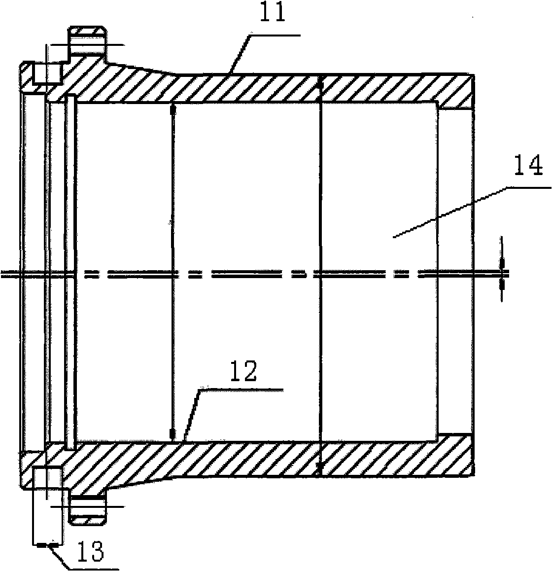
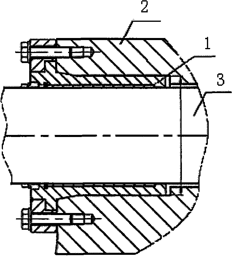
[0018] refer to figure 1 , figure 2 : An eccentric bushing 1 of an adjustable pitch mechanism, the pitch mechanism includes a pitch adjusting frame 2 with a guide hole and a guide rod 3, wherein the eccentric bushing 1 is installed in the guiding hole of the pitch adjusting frame 2, And the guide rod 3 is installed in the eccentric bush inner hole 14, the diameter of the outer ring 11 of the eccentric bu...
PUM
 Abstract
Description
Claims
Application Information
PatSnap Eureka turns technology decisions into work you can execute. Powered by our Innovation Knowledge Graph, it runs expert workflows across engineering, life sciences, materials and intellectual property. Get your review-ready output in minutes.


