In-line measuring devices and method for compensating measurement errors in in-line measuring devices

A technology of measuring equipment and measuring tubes, applied in the direction of measuring flow/mass flow, measuring capacity, measuring device, etc., which can solve the problems such as the inability to perfectly eliminate the mass flow error, the inability to explain the positive error, the bending of the measuring tube, etc.

Active Publication Date: 2008-12-31
ENDRESS HAUSER FLOWTEC AG
View PDF49 Cites 8 Cited by
  • Summary
  • Abstract
  • Description
  • Claims
  • Application Information

AI Technical Summary

Problems solved by technology

However, this is a very special solution which cannot always be realized in industrial process measurement technology
On the one hand, in this case, it may happen that the pipe in which the vibration transducer is inserted may be suitable for this vibration transducer, and not the other way around, which may mean an increase in the cost for realizing the measurement position
On the other hand, as already mentioned, the measuring tube may have a curved shape, in which case the problem cannot always be solved satisfactorily no matter how the mounting orientation is adjusted
Moreover, it has been found in this case that no matter how vertically mounted straight measuring tubes are used, the prevention of the aforementioned degradation of the measuring signal cannot be necessarily ensured.
[0011] Furthermore, it has been found that although mass flow errors are compensated based on the reference density and the intuitive density, especially applying this scheme taking account of said bubble effect, the mass flow errors cannot be perfectly eliminated in some cases
In particular, it has been found that the "bubble theory" can only explain the negative density and mass flow errors, while it cannot explain the positive errors observed in several experiments
In fact, compensation schemes based on this theory often overestimate the negative mass flow error

Method used


Image

  • In-line measuring devices and method for compensating measurement errors in in-line measuring devices
  • In-line measuring devices and method for compensating measurement errors in in-line measuring devices
  • In-line measuring devices and method for compensating measurement errors in in-line measuring devices

Examples


Embodiment Construction

[0078] While the invention allows various modifications and alternative forms, the exemplary embodiments of the invention are shown by way of example in the drawings and will be described in detail herein. It should be understood, however, that there is no intent to limit the invention to the particular forms disclosed, but on the contrary all modifications, equivalents, and alternatives are intended to be covered within the spirit and scope of the invention as defined by the claims.

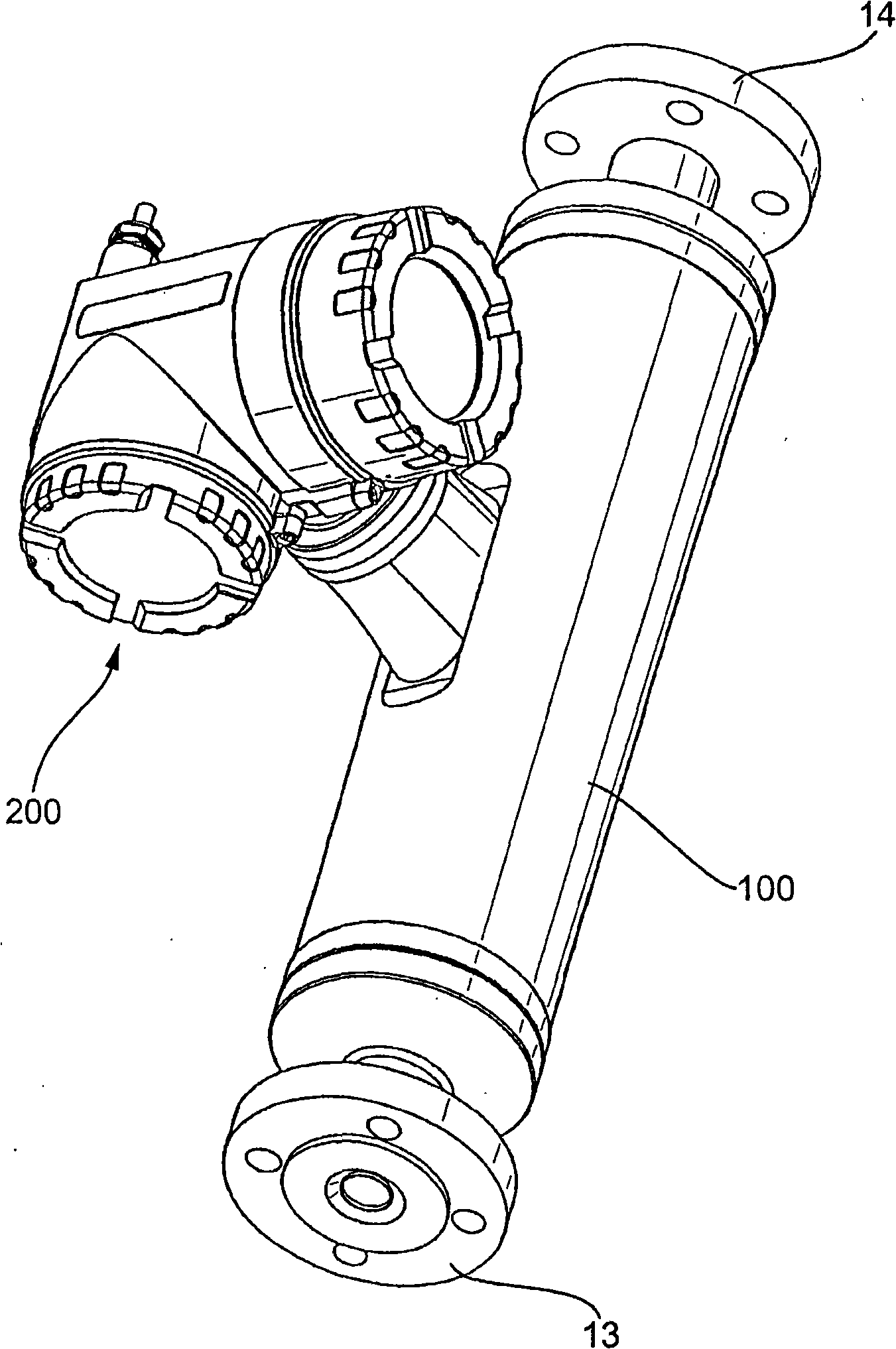
[0079] figure 1 In each case an on-line measuring device 1 is shown, which is suitable for determining a physical measurement of a medium flowing in a pipeline (not shown), for example the mass flow rate , density ρ and / or viscosity η, and is used to reflect this measurement as a measured value X of the transient representation X , in particular, are the mass flow values ​​X m , density value X ρ and / or viscosity value X η . The medium in this example can be virtually any flowable substanc...


PUM


Abstract

The measuring device for measuring multi phase mixture, which comprises a vibratory-type transducer and a measuring device electronics electrically coupled with the vibratory- type transducer. The transducer includes at least one measuring tube inserted into the course of the pipeline. An exciter arrangement acts on the measuring tube for causing the at least one measuring tube to vibrate . A sensor arrangement senses vibrations of the at least one measuring tube and delivers at least one oscillation measurement signal representing oscillations of the measuring tube. Further, the measuring device electronics delivers an excitation current driving the exciter arrangement. The measuring device is adapted to compensating measurement errors, induced due to the presence of multi phase mixture, based on a moving resonator model (MRM).

Description

technical field [0001] The invention relates to an on-line measuring device with a vibration transducer, in particular a Coriolis mass flow / density measuring device for media, in particular two-phase or multi-phase media flowing in pipelines, and to a A method of producing measured values ​​representing physical measured quantities of a medium, such as mass flow rate, density and / or viscosity, by means of the vibratory transducer. Furthermore, the invention relates to a method for compensating measurement errors caused by two-phase or multiphase mixtures in the on-line measuring device. Background technique [0002] In the technology of process measurement and automation, by means of a vibration transducer (which is hereinafter referred to as a vibration transducer) which is inserted into a pipeline carrying a medium and traverses it during operation, and by means of the measuring and An operating circuit, using the on-line measurement device, in particular a Coriolis mass ...

Claims


Application Information

Patent Timeline
IPC IPC(8): G01F1/84G01F1/74
CPCG01F1/849G01F1/74G01F1/8409G01F1/8413G01F1/8418G01F1/8431G01F1/8436G01F15/024
Inventor 沃尔夫冈·德拉赫姆阿尔弗雷德·里德
Owner ENDRESS HAUSER FLOWTEC AG
Why Eureka
Try Eureka