Intelligent clamping device of numerically controlled machine tool

A clamping device, CNC lathe technology, applied in positioning device, clamping, metal processing mechanical parts, etc., can solve the problems of high manufacturing cost, low work efficiency, laborious operation, etc., and achieve low manufacturing cost and realize automatic work. Effect

Inactive Publication Date: 2009-01-07
郭文龙
View PDF0 Cites 10 Cited by
  • Summary
  • Abstract
  • Description
  • Claims
  • Application Information

AI Technical Summary

Problems solved by technology

[0002] The clamping device structure of traditional machine tools is generally manually operated, and the clamping operation is troublesome and the work efficiency is low.
Among the currently used CNC lathes, some clamping devices use horizontal rods, some use immediate rods, and some use rotary cylinder structures. Compared with the traditional manual operation structure, these three structures have great advantages. Great improvement, but at the same time, it also has the disadvantages of high manufacturing cost, laborious and troublesome operation, and it is increasingly unable to meet the needs of fully automatic machining of CNC machine tools. The holding force is generally processed according to the operator's experience and intuition during operation. This is not a big problem for skilled workers, but it is very difficult for novices. Excessive blessing, resulting in deviations in the accuracy of processed products, or even scrapping, resulting in unnecessary waste

Method used


Image

  • Intelligent clamping device of numerically controlled machine tool

Examples


Embodiment Construction

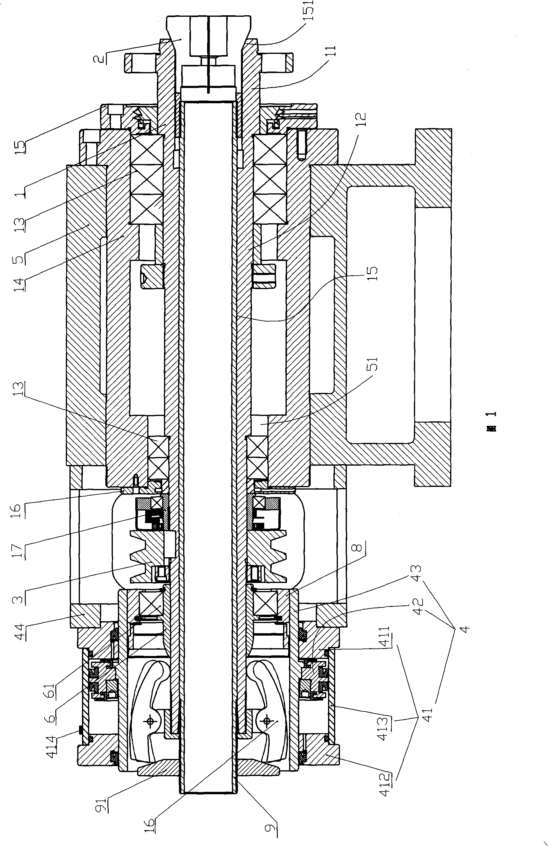
[0015] As shown in Figures 1 and 2, it is an intelligent clamping device for a CNC lathe. The entire clamping device includes a hollow rotating spindle 1, a chuck 2 for clamping a workpiece, a pulley 3 connected to a power motor, and a piston. Cylinder 4.

[0016] The rotating spindle 1 includes a head 11 and a trunk 12, wherein the front section of the trunk 12 is flexibly connected to a spindle sleeve 14 through several rolling bearings 13 and is positioned in the mounting hole 51 of the head of the bed 5, while the rotating spindle head 11 is The installation hole 51 protruding from the head of the bed, here, in order to ensure the lubrication of the movable connection between the main shaft body 12 and the main shaft sleeve 14, the main shaft front cover 15 and the Main shaft back cover 16 realizes oil seal. The said pulley 3 is installed in the middle part of the main shaft body part 12, and the pulley 3 is connected to the power motor by a belt, and is used to drive the...


PUM


Abstract

The invention discloses an intelligent clamping device of a numerical control machine tool. The entire device comprises a rotating main shaft, a clamping chuck, a belt pulley and a piston cylinder, wherein the rotating main shaft comprises a head and a body, wherein the front section of the body is movably connected with a shaft sleeve and positioned in a mounting hole of a tool head; the belt pulley is mounted at the middle section of the body of the main shaft; the rear section thereof is connected with the piston cylinder; an inner hole of the rotating main shaft is a straight through-hole; the clamping chuck is mounted in an opening at the front end of the straight through-hole; the rear part of the clamping chuck is connected with a pull pipe; the pull pipe extends from the inner hole of the main shaft backwards into the piston cylinder; an inclination disk is connectedly arranged at the tail end of the pull pipe; a three-jaw structure is arranged at the tail end of the rotating main shaft in a thread connection manner and can form a movable fit with the inclination disk. By structurally adopting the electromechanical integration design, the clamping device has the advantages of low manufacture cost, as well as convenient, practical, quick and labor-saving clamping of the clamping chuck; meanwhile, the clamping force can be directly measured in the clamping process, so that the clamping device is favorable for operators to use.

Description

technical field [0001] The invention relates to a clamping device, in particular to an intelligent clamping device for a numerically controlled lathe. Background technique [0002] The clamping device structure of traditional machine tools is generally operated manually, and the clamping operation is troublesome and the work efficiency is low. Among the currently used CNC lathes, some clamping devices use horizontal rods, some use immediate rods, and some use rotary cylinder structures. Compared with the traditional manual operation structure, these three structures have great advantages. Great improvement, but at the same time, it also has the disadvantages of high manufacturing cost, laborious and troublesome operation, and it is increasingly unable to meet the needs of fully automatic machining of CNC machine tools. The holding force is generally processed according to the operator's experience and intuition during operation. This is not a big problem for skilled workers...

Claims


Application Information

Patent Timeline
Patent Type & Authority Applications(China)
IPC IPC(8): B23Q3/12
Inventor 郭文龙
Owner 郭文龙
Why Eureka
Try Eureka