Warp knitting machine

A warp knitting machine and bar technology, which is applied in the field of warp knitting machines, can solve the problems of high yarn consumption and achieve the effect of easy operation

A warp knitting machine and bar technology, which is applied in the field of warp knitting machines, can solve the problems of high yarn consumption and achieve the effect of easy operation

CN101338486AInactive Publication Date: 2009-01-07KARL MAYER TEXTILMASCHFAB GMBH

Image

  • Warp knitting machine
  • Warp knitting machine

Examples


Embodiment Construction

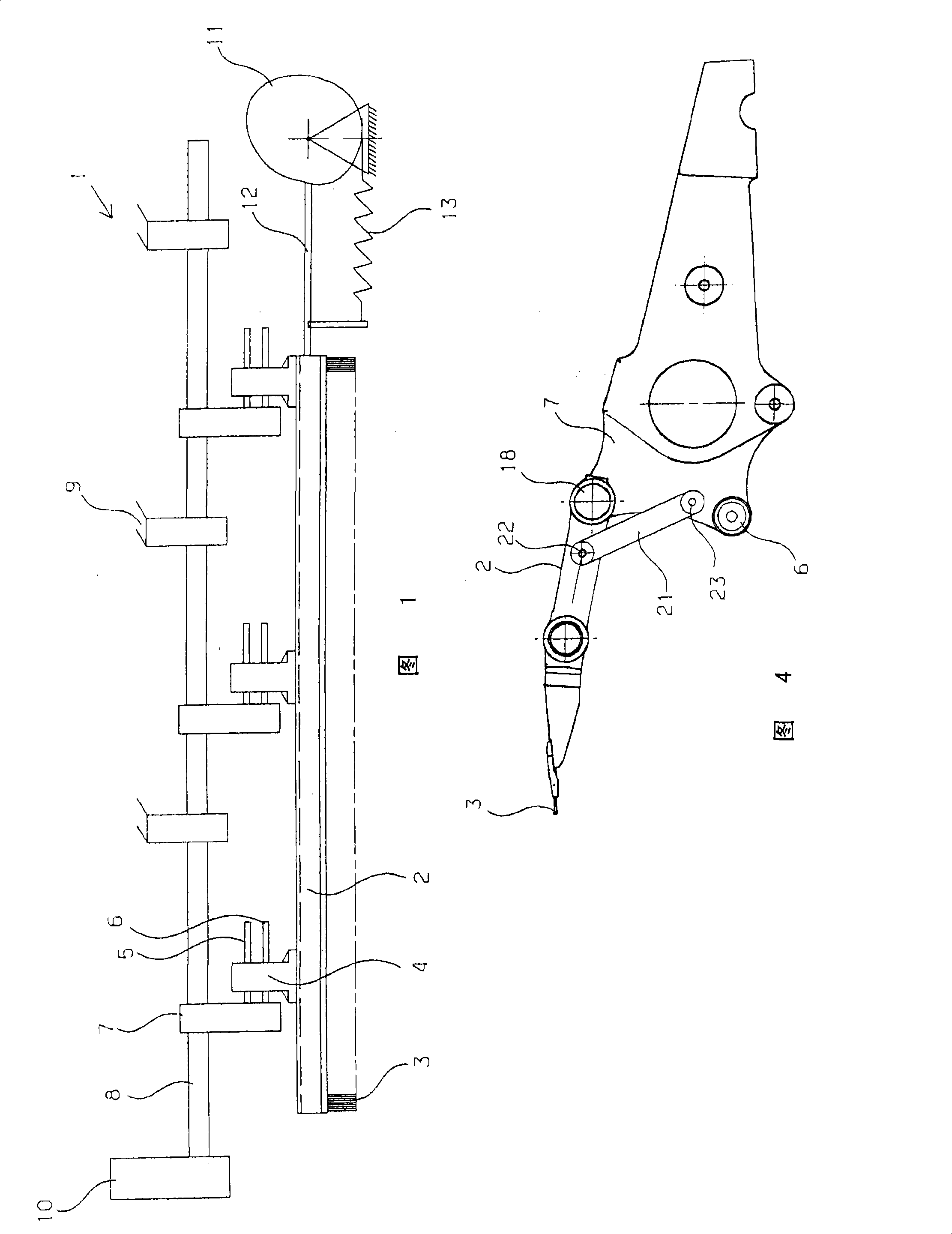
[0029] FIG. 1 shows a section of a warp knitting machine 1 with a bar 2 , which supports a plurality of bar needles 3 , in a significantly simplified schematic view. The comb needle 3 is made of a hole needle.

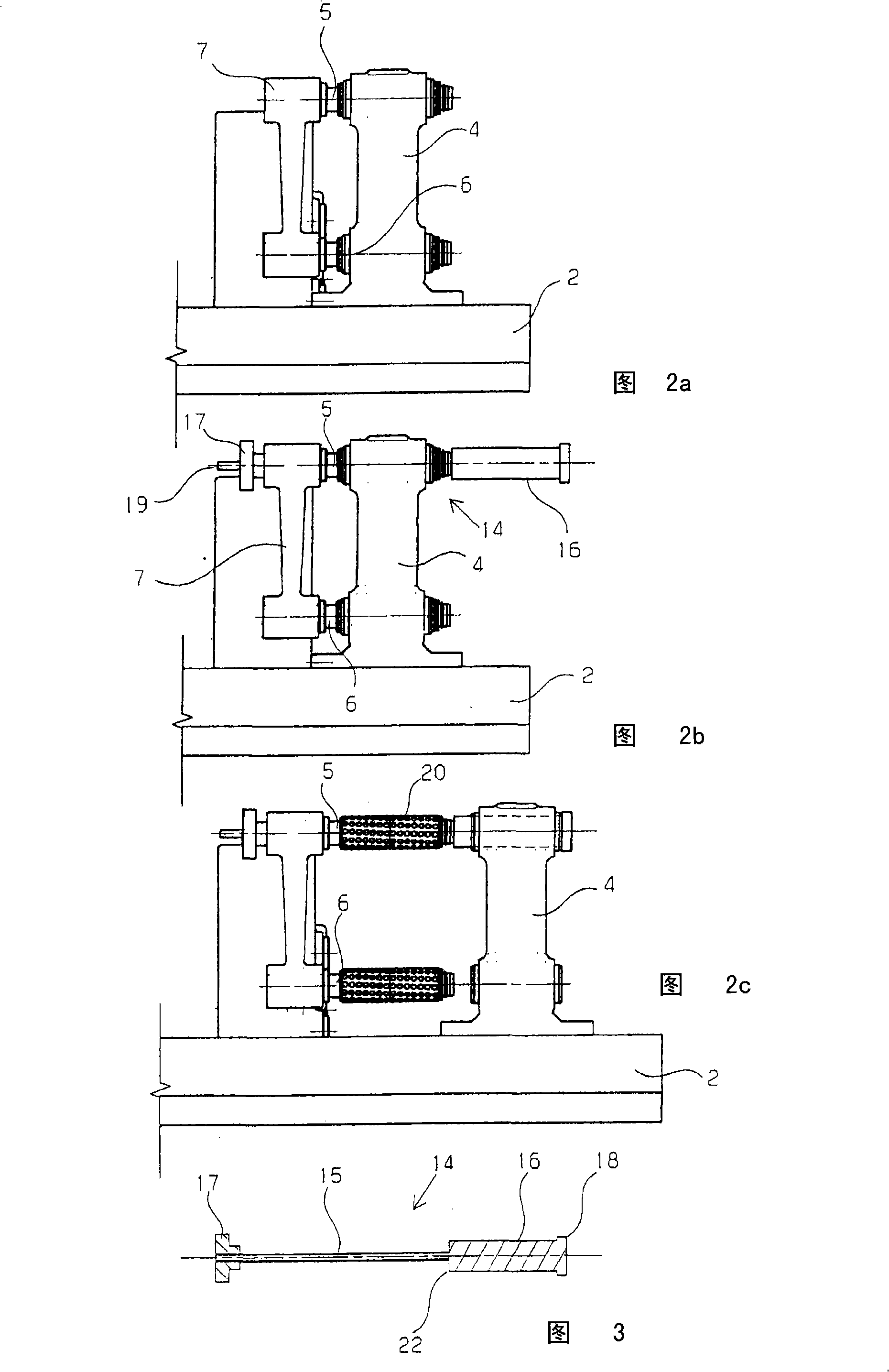
[0030] The bar has a plurality of bar frames 4 distributed over the length of the bar as guides. Other guides are also possible. Each bar frame is attached to two guide pins 5 , 6 , wherein the guide pins 5 , 6 are shown exaggerated in the illustration in FIG. 1 .

[0031] The guide pins 5 , 6 are each fastened to a comb bar 7 which is connected to a suspension shaft 8 in a torsion-proof manner. The suspension shaft 8 is suspended on bearings 9 and can be rotated back and forth over a small angular range by means of a rotary drive 10 . During rotation, the bar is deflected and the bar 2 is deflected by the bar 7 .

[0032] During operation, the bar 2 is driven parallel to its longitudinal extension by a jacquard wheel 11 , which acts on the bar 2 via a jack 12 . A...


PUM


Abstract

The present invention provides a knitting machine (1), which has a guide bar (2) comprising guide needles and suspended at guide levers (7), where each guide lever (7) is connected with the guide bar by at least a guide pin (5, 6) and has an anti-swivel mechanism for the guide bar (2). In operation of the knitting machine, breaks are desired to be kept short. Thus the guide pin (5) has a detachable projection (14) with which the guide bar (2) is adjusted beyond a normal displacement channel in a connected condition.

Description

technical field [0001] The invention relates to a warp knitting machine with at least one bar, which has bar needles and is suspended on bar bars, wherein each bar bar is connected to the bar by at least one guide pin and has a The rotary fixed part of the bar. Background technique [0002] Such a warp knitting machine is known from DE 3828469C2. Here, each bar bar has two guide pins on which a guide fixed to the bar is guided by means of a ball socket and extends parallel to the longitudinal direction of the bar. In principle, however, it is also possible to connect the guide pin fixedly to the guide of the bar and to arrange the corresponding bearing in the bar. [0003] During operation, the bar needles fastened to the bar must be moved not only in the machine direction, ie parallel to the longitudinal extension of the bar, but also perpendicularly thereto. The first movement thus acts to deflect the bar relative to the bar. The second movement thus acts, deflecting t...

Claims


Application Information

Patent Timeline
07 Jan 2009
Publication
CN101338486A
IPC
D04B27/24
CPC
D04B27/24
Inventors
M·哈克; K·布兰德尔