

Cyclone compressor possessing lubricating system
A scroll compressor and lubrication system technology, applied in the field of scroll compressors, achieves the effects of high compression efficiency, reduced wear and reduced power consumption
- Summary
- Abstract
- Description
- Claims
- Application Information
AI Technical Summary
Problems solved by technology
Method used
Image

Examples
Embodiment 1
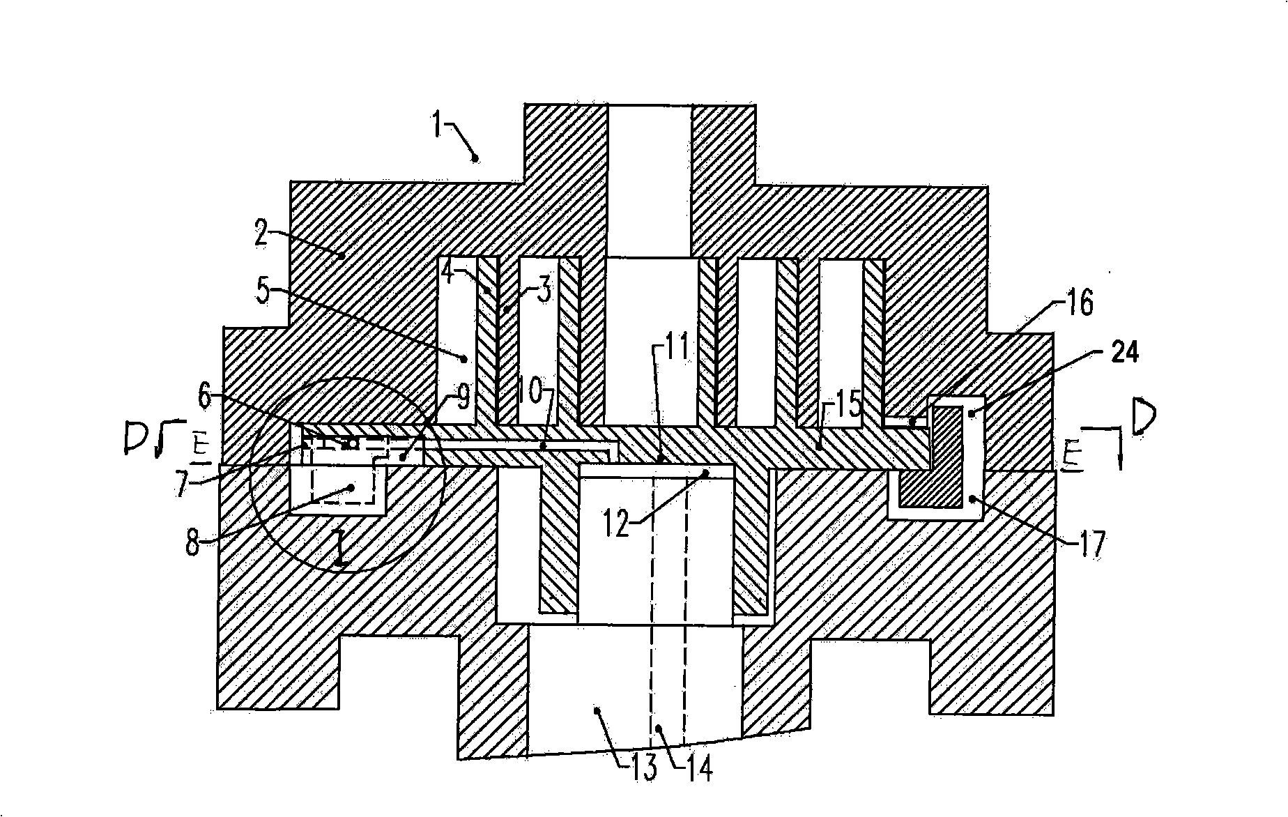
[0035] Such as figure 1 A scroll compressor shown includes a fixed scroll member 2 with a spiral wrap 3, a movable scroll member 15 with a spiral wrap 4, the fixed scroll member and the movable scroll member The spiral scroll teeth cooperate with each other to form a compression chamber. The movable scroll part circulates relative to the fixed scroll part under the action of the drive shaft. A cross is installed in the top groove of the fixed scroll part and the bottom groove of the movable scroll part. The ring part can prevent the movable scroll part 15 from rotating. There is a communication hole on the movable scroll part. The drive shaft 13 has an oil inlet passage 14. One end of the communication hole is connected to the oil inlet passage, and the other end is connected to the chamber. The lubricating oil is supplied to the chamber. There is an oil passage on the movable scroll part. The oil hole at the end of the oil passage communicates with the groove, and the other e...
Embodiment 2
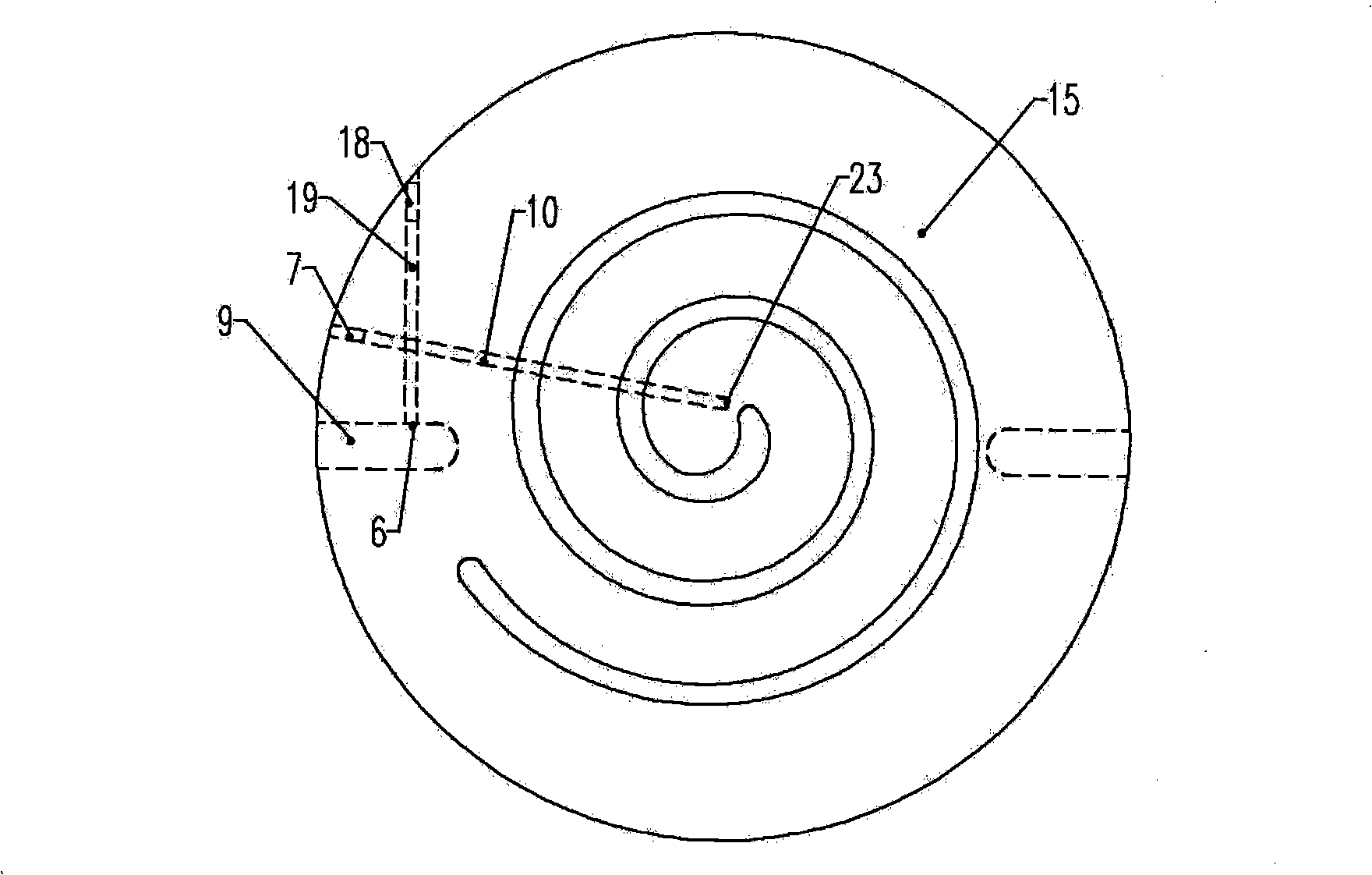
[0040] Such as Figure 5 As shown, the oil hole 6 on the side of the groove 9 on the bottom surface of the movable scroll part 15 is facing the side of the slider of the cross ring sliding part. The side facing the cross ring sliding part 8, the oil hole is not completely closed to provide lubricating oil; during the rest of the rotary cycle, the oil hole faces the side of the cross ring sliding part, the oil hole is completely closed, in this compressor Here, lubricating oil is only provided during the limited phases of the scroll compressor cycle, when the holes are alternately opened and closed, relying on constraints such as pressure differences to regulate the flow of oil and control the amount of oil. The lubricating oil is supplied to the mating surface formed by the fixed scroll member and the movable scroll member through the channel communicated with the groove provided on the top of the fixed scroll member.
Embodiment 3
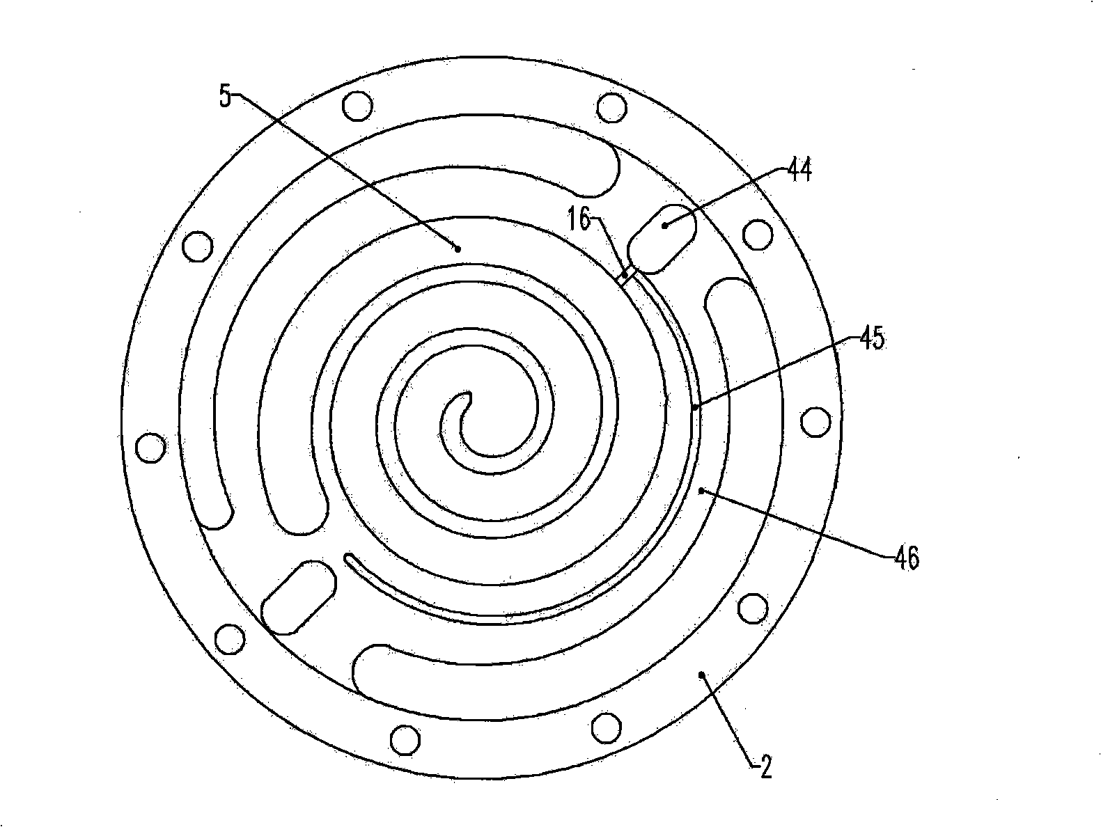
[0042]Such as Figure 6 As shown, the oil hole 6 on the side of the groove 9 on the bottom surface of the movable scroll part 15 faces the side of the cross ring sliding part. During the whole revolution cycle, the cross ring sliding part slides in the groove of the movable scroll element , during the whole cycle of the cross-ring sliding part 8, the side of the cross-ring sliding part does not cover the oil hole, and the lubricating oil is always supplied in the whole cycle of the movable scroll element's rotary motion. By controlling the diameter of the oil hole and the pressure difference at both ends of the oil hole, the amount of oil entering the groove at the bottom of the movable scroll element is controlled.
PUM
| Property | Measurement | Unit |
|---|---|---|
| Diameter | aaaaa | aaaaa |
Abstract
Description
Claims
Application Information