Spring

A technology of elastic material and liquid damping, which is applied in springs, springs/shock absorbers, and spring components composed of several springs, etc., can solve the problems of insufficient damping ratio and complex structure, and achieve the purpose of preventing spring oxidation and corrosion and simplifying the structure , The effect of noise reduction

Active Publication Date: 2009-01-07
尹学军
View PDF0 Cites 11 Cited by
  • Summary
  • Abstract
  • Description
  • Claims
  • Application Information

AI Technical Summary

Problems solved by technology

In practice, in order to increase its damping, it is sometimes used to put a layer of rubber tube on the outside of the spring or vulcanize ordinary rubber on the surface of the spring, but ordinary rubber is fundamentally a viscoelastic material with low damping and high elasticity. Under high-frequency action conditions, such as vibration and noise in the audio frequency range, there will be a certain damping effect. For most mechanical vibrations, the damping ratio is only 1-3%, and the damping ratio is even smaller when used in parallel with the spring. In most cases, the damping ratio is far from enough. For example, for the vibration reduction and vibration isolation of general vehicles and equipment, the damping ratio is required to be between 10% and 30%. At this time, it must be used with additional damping devices, which makes the structure complicated.

Method used


Image

  • Spring
  • Spring
  • Spring

Examples


Embodiment 1

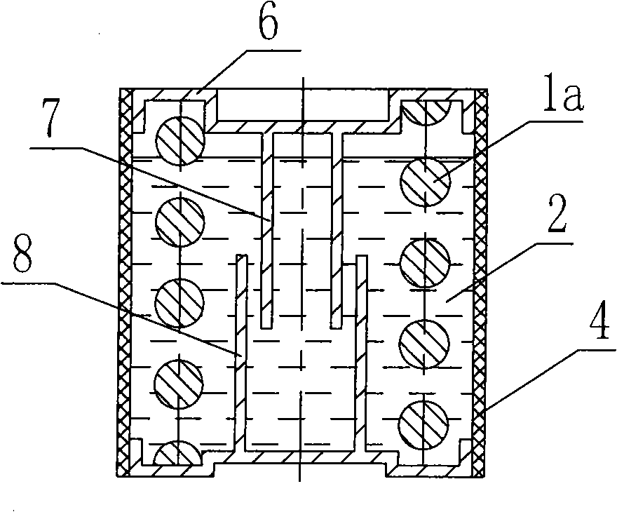
[0034] The overall structure of Embodiment 1 of the present invention is as follows figure 1 As shown, it comprises a helical spring 1a and a damping material 2, the helical spring 1a being partly immersed in the liquid damping material 2. The liquid damping material 2 is provided with a tubular sealing protection layer 4 and upper and lower end plates 6 which simultaneously function as sealing and centering. In order to increase the damping shear area, the inner and outer damping cylinders 7 and 8 extending into the liquid are respectively arranged on the upper and lower end plates 6. When the coil spring 1a is deformed under force, the spring body and the inner and outer damping cylinders 7 and 8 will make the liquid The damping material 2 generates relative shearing motion and rubs against the coil spring 1a and the sealing protection layer 4. Since the liquid damping material 2 has a large internal friction, it will generate a damping force that is always opposite to the d...

Embodiment 2

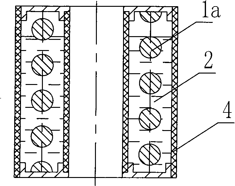
[0037] Such as figure 2 As shown, the spring wire of the coil spring 1a is partially immersed in the liquid damping material 2, and the liquid damping material 2 is located in the interlayer between two large and small sealing protection layers 4, and the upper and lower ends of the interlayer are sealed and centered with a metal ring 6

Embodiment 3

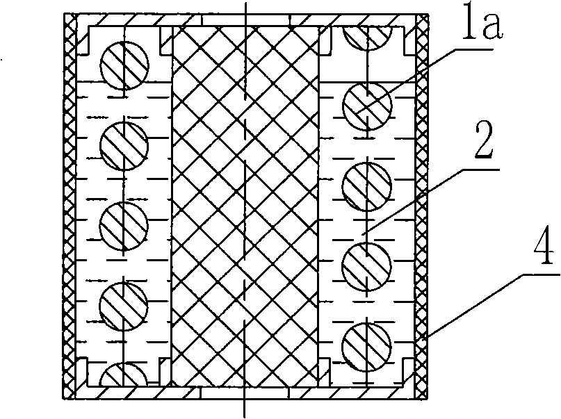
[0039] Such as image 3 As shown, the spring wire part of the coil spring 1a is immersed in the liquid damping material 2, and the liquid damping material 2 is located in the interlayer between the outer peripheral sealing protection layer 4 and the central high damping rubber column 5, and the upper and lower ends of the interlayer are sealed with metal rings 6. middle. This embodiment has greater damping due to the additional damping provided by the high damping rubber post in the center.


PUM


Abstract

The present invention belongs to a spring. A damping structure, which can damp the motion of the spring and contains high-damp liquid material, is arranged on the body of the spring. Since the damping structure is arranged on the body of the spring, when the spring is stressed to generate vibration or deformation, the high-damp liquid material is also deformed, great internal friction is generated inside the high-damp liquid material to absorb partial energy, so that the deformation is hindered and the vibration is attenuated, and since noise is also caused by the vibration, the noise is greatly reduced as well. Since the spring adopts the highly viscous high-damp liquid material, the spring can provide a relatively high damping ratio, which is sufficient for the vibration reduction of most of mechanical devices and vehicle structures, and even in a case requiring a high damping ratio, the needed extra damp is much less. Normally, an additional damping device is no longer needed, and therefore the structure is simplified. Moreover, the spring effectively eliminates the sympathetic vibration of self under the inherent frequency.

Description

technical field [0001] The present invention is a divisional application whose application number is 200310105524.9, and belongs to damping springs. Background technique [0002] Ordinary springs are generally made of pure elastic materials, and their damping is very small, especially metal springs. In practice, in order to increase its damping, it is sometimes used to put a layer of rubber tube on the outside of the spring or vulcanize ordinary rubber on the surface of the spring, but ordinary rubber is fundamentally a viscoelastic material with low damping and high elasticity. Under high-frequency action conditions, such as vibration and noise in the audio frequency range, there will be a certain damping effect. For most mechanical vibrations, the damping ratio is only 1-3%, and the damping ratio is even smaller when used in parallel with the spring. In most cases, the damping ratio is far from enough. For example, for the vibration reduction and isolation of general vehi...

Claims


Application Information

Patent Timeline
Patent Type & Authority Applications(China)
IPC IPC(8): F16F3/07
Inventor 尹学军
Owner 尹学军
Why Eureka
Try Eureka