Control apparatus

一种控制装置、控制部的技术,应用在程序控制、控制系统、数字控制等方向,能够解决减低控制对象、无法检测到控制对象固有振动频率、错误固有振动频率等问题,达到减低固有振动的效果

Active Publication Date: 2009-01-07
FANUC LTD
View PDF1 Cites 18 Cited by
  • Summary
  • Abstract
  • Description
  • Claims
  • Application Information

AI Technical Summary

Problems solved by technology

[0017] In addition, the reason is that, depending on the state of the controlled object, resonance based on the natural frequency does not occur, so even if the detection is performed, the natural frequency of the controlled object may not be detected
[0018] In addition, in the process of reducing the natural vibration of the controlled object, the controlled object may become unstable
As an example, when the correct natural frequency cannot be detected, the wrong natural frequency is detected, and the filter setting is changed, the controlled object becomes unstable.
As another example, even when the correct natural frequency is detected, when the natural frequency is close to the control frequency band, the filter removes part of the signal in the control frequency band, and the controlled object becomes unstable.

Method used


Image

  • Control apparatus
  • Control apparatus
  • Control apparatus

Examples


no. 1 approach

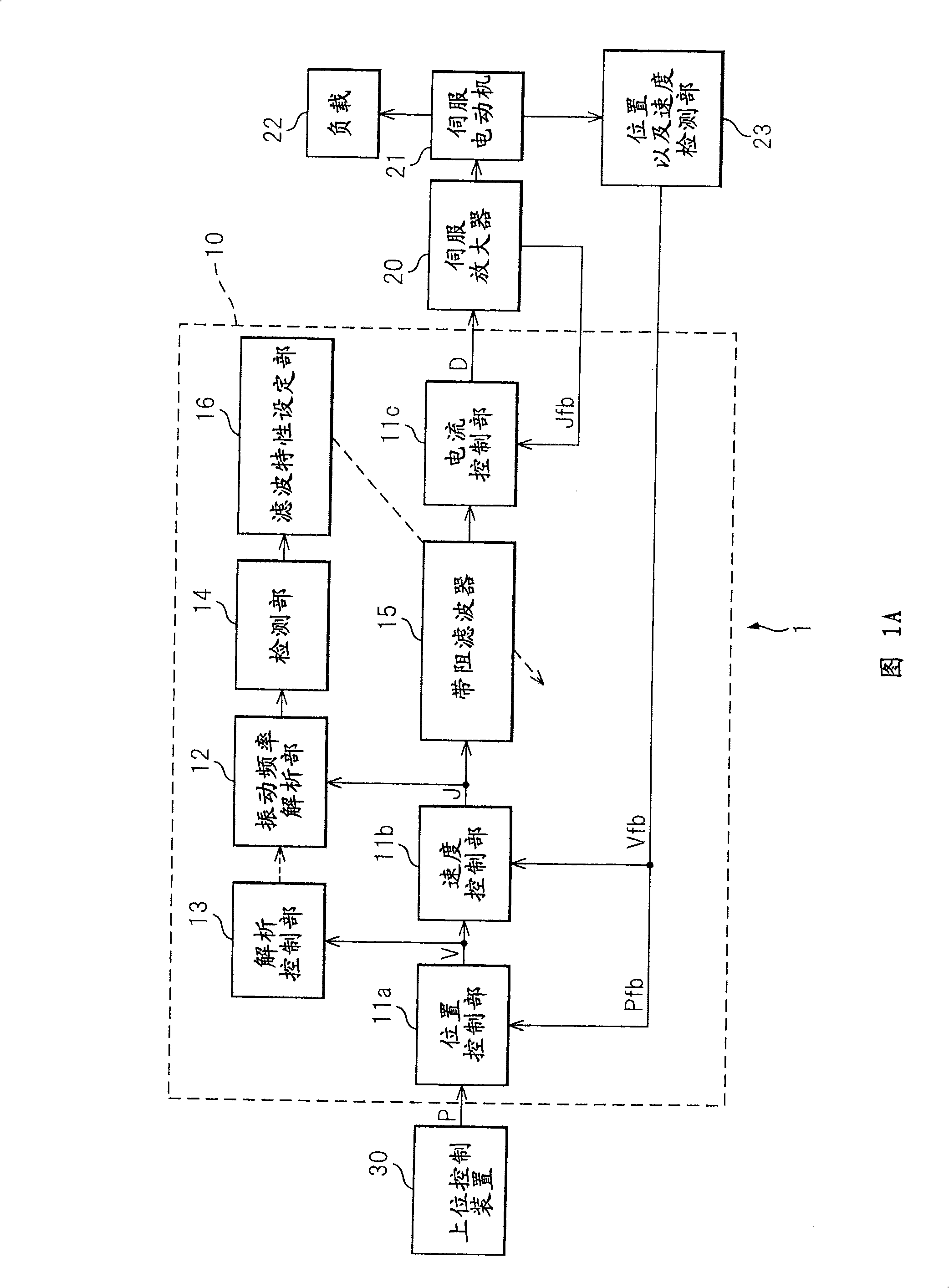
[0048] The control device 10 (hereinafter referred to as the present device 10 ) of the first embodiment of the present invention is a control device of the machine tool 1, and as shown in FIG. 20. Control the servo motor 21 as the motor, drive the load 22 as the driven part to control its action.

[0049] As shown in FIG. 1A , this device 10 has a control unit that outputs a control signal for controlling the servo motor 21 , and controls the control target while suppressing the natural vibration of the control target including the servo motor 21 and the machine driven by the servo motor 21 .

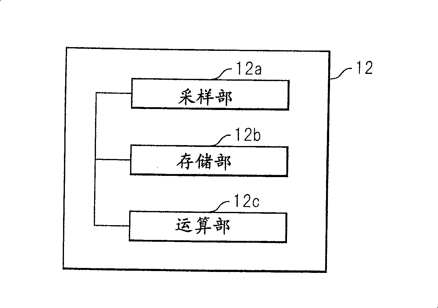
[0050] In addition, this device 10 has: a vibration frequency analysis unit 12 for analyzing the vibration frequency component contained in the torque command as a control signal; an analysis control unit 13 for controlling the execution or stop of the vibration frequency analysis unit 12 Detector 14 is used to detect the natural frequency of the control object according to the analysi...

no. 2 approach

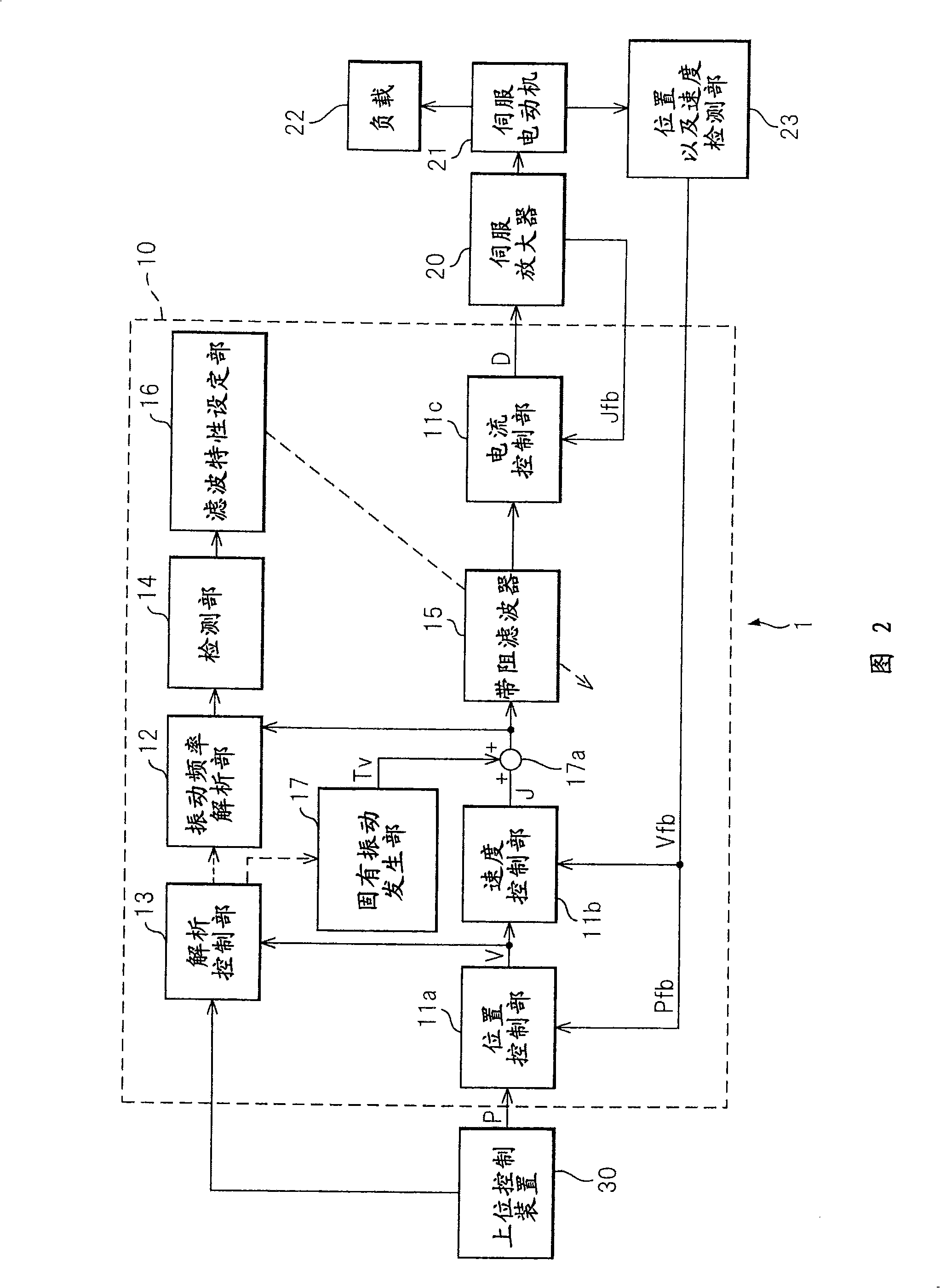
[0096] As shown in FIG. 2 , the control device 10 (hereinafter also referred to as the present device 10 ) according to the second embodiment of the present invention has a high-level control device 30 that controls the analysis control unit 13, and the high-level control device 30 outputs to the analysis control unit 13 When the instruction is executed, the analysis control unit 13 causes the vibration frequency analysis unit 12 to execute the vibration frequency analysis. The host control device 30 of the device 10 outputs the position command P to the position control unit 11 a and also controls the analysis control unit 13 , as in the above-mentioned first embodiment.

[0097] The device 10 is further described below.

[0098] Similar to the above-described first embodiment, when a vibration having a large amplitude other than the natural vibration to be controlled is known, the analysis control unit 13 controls the vibration frequency analysis unit 12 so as not to detect ...

no. 3 approach

[0113] In the control device 10 (hereinafter also referred to as the present device 10 ) according to the third embodiment of the present invention, the detection unit 14 detects the natural frequency of the control object from the range of the predetermined vibration frequency in the analysis result of the vibration frequency analysis unit 12 .

[0114] Refer below image 3 The present device 10 will be described. image 3 An example of analysis results by the vibration frequency analysis unit 12 is shown. exist image 3 In , there are peaks PF1 , PF2 , and PF3 , and the magnitudes of the respective vibration frequency components are equal to or greater than a threshold Th at which the detection unit 14 judges as a natural frequency. Threshold Th at image 3 In the example shown, there is a constant value for the vibration frequency.

[0115] Here, it is assumed that the peak PF1 and the peak PF3 are known to be the natural frequency of the controlled object, and the pea...


PUM


Abstract

A control apparatus of the present invention comprising a control unit outputting a control signal controlling a servo motor and suppressing natural vibration of a controlled object including a motor and a machine driven by the motor while controlling the controlled object, comprising a frequency analysis unit analyzing a frequency component included in a torque command, an analysis control unit controlling the start or stopping of the frequency analysis unit, a detection unit detecting a natural frequency of the controlled object from an analysis result of the frequency analysis unit, a band rejection filter receiving as input the torque command, stripping the command of the natural frequency component, and outputting the resultant command to the motor through a current control unit and servo amplifier, and a filter characteristic setting unit setting the frequency to be stripped at the filter based on the natural frequency detected by the detection unit.

Description

[0001] This application claims priority based on Japanese Patent Application No. 2007-174296 filed on July 2, 2007, the entire contents of which are hereby incorporated by reference into this application. technical field [0002] The present invention relates to a control device, and more particularly to a control device for controlling a control target including a motor and a machine driven by the motor while suppressing the natural vibration of the control target. Background technique [0003] Currently, in a machine tool having an electric motor, a control device for the electric motor is used. In particular, a control device that uses a servo motor as a motor for feedback control, in order to always make the difference between the command value and the actual value of position, speed, current, etc. to be zero, so it is necessary to accurately control the mechanical position or motor speed, etc., so It is widely used in general CNC machine tools and the like. [0004] On...

Claims


Application Information

Patent Timeline
Patent Type & Authority Applications(China)
IPC IPC(8): G05D19/02G05B19/416H02P29/00
CPCG05B2219/41166G05B2219/41232G05B13/024G05B19/19G05B2219/34048G05B2219/37534
Inventor 置田肇丰泽雪雄园田直人
Owner FANUC LTD
Why Eureka
Try Eureka