Rotary table bearing with high limit speed

A technology for limiting rotational speed and turntable bearings, applied in the field of bearings, it can solve the problems of temperature rise in the bearing raceway, burns of parts such as raceways and rollers, spin motion of cylindrical rollers, etc., and achieve edge contact stress reduction and service life. The effect of prolongation and speed increase

Active Publication Date: 2019-12-06
HENAN UNIV OF SCI & TECH
View PDF19 Cites 0 Cited by
  • Summary
  • Abstract
  • Description
  • Claims
  • Application Information

AI Technical Summary

Problems solved by technology

The upper and lower rows of axial rollers of this kind of bearing will have a speed difference between the two ends during the rotation process, which will lead to the occurrence of cylindrical roller spin motion, and then form sliding friction, which makes the friction torque of the bearing larger and the limit operating speed lower
Once the speed of the bearing is too high, the temperature of the raceway of the bearing will rise sharply, causing burns to parts such as the raceway and rollers.
However, with the increasing speed of CNC machine tools, the speed requirements of CNC turntables are also increasing, and the traditional turntable bearings can no longer meet the urgent needs of production.

Method used


Image

  • Rotary table bearing with high limit speed
  • Rotary table bearing with high limit speed
  • Rotary table bearing with high limit speed

Examples


Embodiment Construction

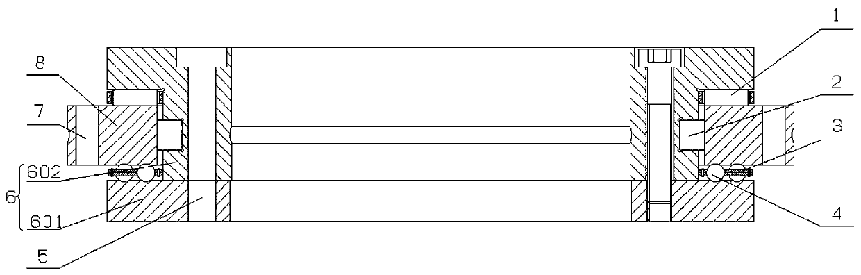
[0026] Such as figure 1 As shown, a turntable bearing with a high limit speed of the present invention is similar in main structure to a conventional turntable bearing, both including an inner ring 6 and an outer ring 8 rotatably arranged on the outer periphery of the inner ring 6 . The outer ring 8 is ring-shaped, and the inner ring 6 is I-shaped. The upper edge of the outer ring 8 and the lower edge of the upper end of the inner ring 6 are matched by a plurality of first rolling elements 1. The inner edge of the outer ring 8 and the middle part of the inner ring 6 The outer edge of the outer ring is matched by a plurality of second rolling elements 2, and the lower edge of the outer ring 8 is matched with the upper edge of the lower end of the inner ring 6 by a plurality of third rolling elements 4. For ease of assembly, the inner ring 6 is split and includes an upper ring 602 and a lower ring 601 . The outer ring 8 is provided with a first installation hole 7 for fixing th...


PUM


Abstract

The invention relates to the field of bearings, in particular to a rotary table bearing with a high limit speed. The rotary table bearing comprises an inner ring and an outer ring. Multiple first rolling bodies are arranged between the upper edge of the outer ring and the inner ring at intervals, multiple second rolling bodies are arranged between the inner edge of the outer ring and the inner ring at intervals, multiple third rolling bodies are arranged between the lower edge of the outer ring and the inner ring at intervals, the first rolling bodies and the second rolling bodies are cylindrical rollers, and the third rolling bodies are steel balls, and all the third rolling bodies are cooperatively mounted in split retainers. The split retainers comprise upper frame pieces and lower frame pieces fixed to the upper frame pieces, upper pocket grooves and lower pocket grooves are formed in the corresponding positions of the upper frame pieces and the lower frame pieces separately, pocket holes allowing the third rolling bodies to be cooperatively assembled are formed by the upper pocket grooves and the lower pocket grooves jointly, and notches connected with the pocket holes are further formed in the split retainers. The requirements for the rigidity and the precision can be met, and the high limit speed and low friction torque are achieved.

Description

technical field [0001] The invention relates to the field of bearings, in particular to a turntable bearing with a high limit speed. Background technique [0002] The traditional turntable bearing is a three-row combined roller bearing, which is composed of two thrust cylindrical roller bearings and a full complement radial cylindrical roller bearing. The upper and lower rows of axial rollers of this kind of bearing will have a speed difference between the two ends during the rotation process, which will lead to the occurrence of cylindrical roller spin motion, and then form sliding friction, which makes the friction torque of the bearing larger and the limit operating speed lower. Once the bearing speed is too high, the temperature of the raceway of the bearing will rise sharply, causing burns to parts such as raceways and rollers. However, with the increasing speed of CNC machine tools, the speed requirements of CNC turntables are also increasing, and the traditional tur...

Claims


Application Information

Patent Timeline
Patent Type & Authority Applications(China)
IPC IPC(8): F16C19/49F16C33/58F16C33/38F16C33/46F16C43/04
CPCF16C19/49F16C33/38F16C33/46F16C33/583F16C43/04Y02T10/86
Inventor 张占立张开哲孟思远李文博吕小威马明阳
Owner HENAN UNIV OF SCI & TECH
Why Eureka
Try Eureka