Single side disc protecting box and optical disc read-write apparatus matching therewith

A single-sided technology for reading and writing equipment, applied in the field of mechanical disc fixing mechanism and optical disc reading and writing equipment, can solve the problems of complex mechanical movement, unguaranteed disc release effect, and increased cost, so as to achieve simple structure and easy disc clamping Effect guarantee, the effect of saving manufacturing cost

Inactive Publication Date: 2012-07-04
王诚实
View PDF0 Cites 0 Cited by
  • Summary
  • Abstract
  • Description
  • Claims
  • Application Information

AI Technical Summary

Problems solved by technology

[0006] The mechanical disc fixing mechanism of the single-sided disc protection box is not only bulky, but also the corresponding mechanical movement of the card and the disc is relatively complicated. Therefore, the disc bracket of the disc reading and writing equipment used in conjunction with it also needs to be equipped with a corresponding complicated driving mechanism. And the power mechanism drives the disc body of the single-sided disc protection box to release the optical disc. As a result, various driving mechanisms and power mechanisms are repeatedly set on the optical disc bracket, and it is often necessary to repeatedly mechanically drive the disc to release the optical disc. Therefore, the release effect of the optical disc is not guaranteed, and the manufacturing of the single-sided disc protection box and the optical disc reading and writing equipment has also become very complicated, and the cost has been greatly increased, resulting in an increase in the initial capital investment in the form of geometric multiples. So far, this technology has not been able to be popularized globally, and of course it cannot be realized even in China.

Method used


Image

  • Single side disc protecting box and optical disc read-write apparatus matching therewith
  • Single side disc protecting box and optical disc read-write apparatus matching therewith
  • Single side disc protecting box and optical disc read-write apparatus matching therewith

Examples


Embodiment 1

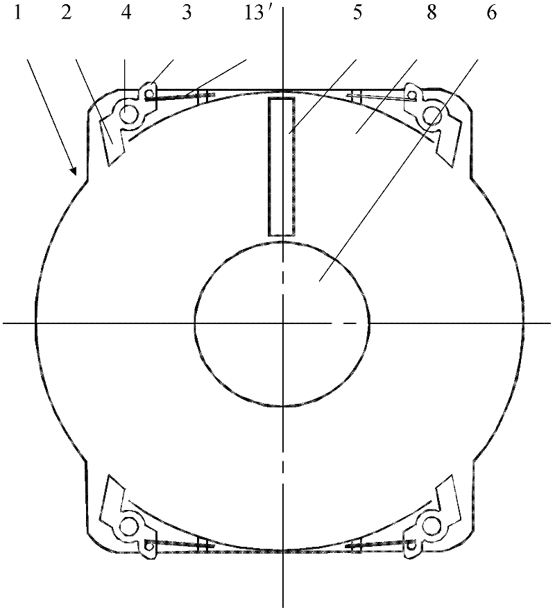
[0062] Such as figure 1 , 2 shown.

[0063] The single-sided disc guard case 1 is provided with a circular disc slot 8, which can hold a disc 7, and the middle part of the disc slot 8 is provided with a circular top disc hole 6, and the diameter of the top disc hole 6 is larger than that of the optical disc. It is advisable that the diameter of the rotating disc motor head of the read-write device is smaller than the diameter of the non-data track area on the inner edge of the optical disc 7. On the radial direction surface of the optical disc groove 8, a read-write head with the same length as the radius of the data track of the optical disc 7 is also provided. Window 5, the width of optical head reading and writing window 5 is advisable to make the optical head of optical disc reading and writing equipment pass through this window to read and write the data of optical disc 7 normally; The periphery of optical disc groove 8 is provided with four expansion areas, for this rea...

Embodiment 2

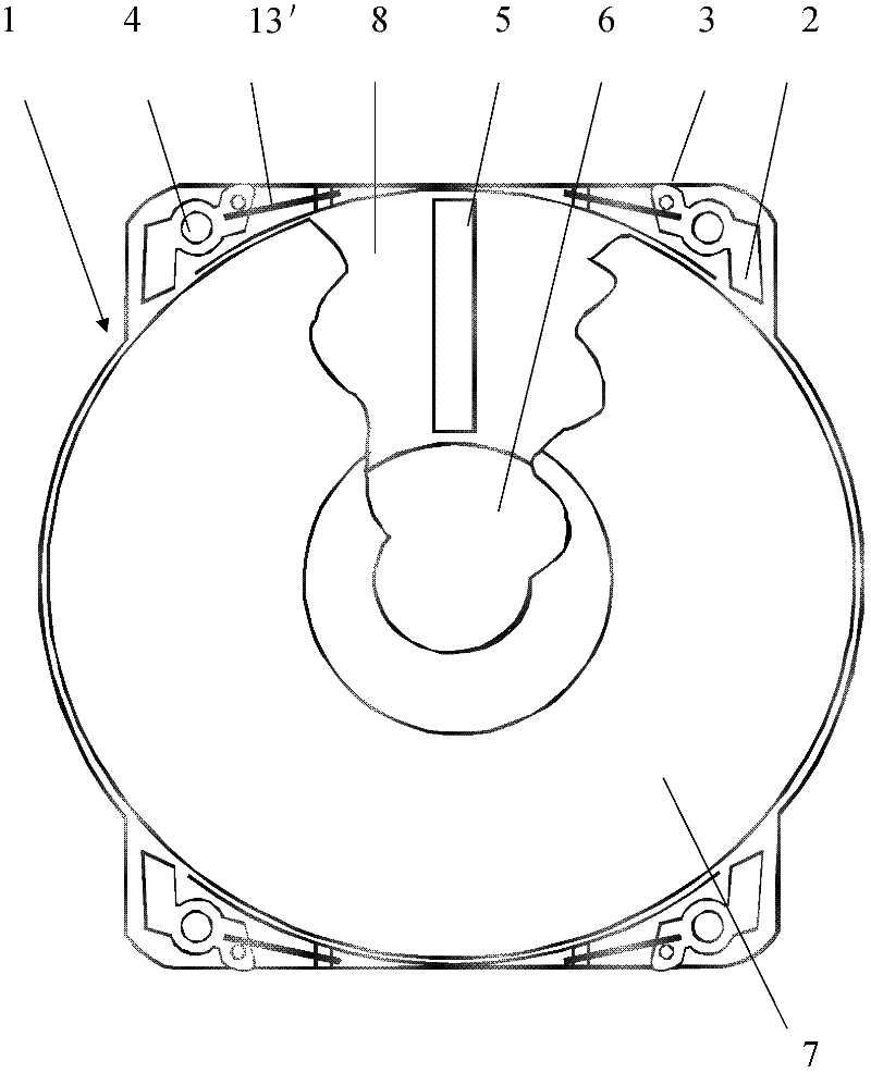
[0073] Such as Figure 8 , 9 , 10 shown.

[0074] With full reference to the basic design scheme of Embodiment 1, the similarities with Embodiment 1 will not be repeated, and the difference is:

[0075] The automatic extruding device that is provided with on the optical disc reading and writing equipment 14 optical disc trays 15 is to be respectively provided with an extruding body 17 to constitute by the vertical direction at the left and right ends of the optical disc tray 15, and the middle of the extruding bodies 17 is a straight strip Shape, and its two ends have crotch, can directly prevent that single-sided disc protection case 1 can slip with the horizontal plane direction of optical disc bracket 15 when being beneficial to extruding single-sided disc protection case 1.

[0076] Each extrusion body 17 is provided with a rotating mechanism 4 near the lower end of the disc holder 15. The extrusion body 17 is flexibly connected with the optical disk holder 15 by the rot...

Embodiment 3

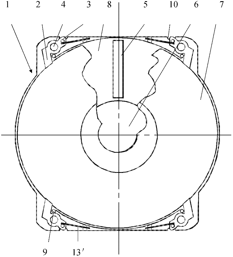
[0080] Such as image 3 , 11 , 12 shown.

[0081] With full reference to the basic design scheme of Embodiment 1, the similarities with Embodiment 1 will not be repeated, and the difference is:

[0082] The specific length of the power body 3 set in the single-sided disc protection box 1 does not exceed the outermost edge of the single-sided disc protection box 1, and each power body 3 is also provided with a squeezing groove 10 at the position of the single-sided disc protection box 1 corresponding to it. , the squeezing groove 10 forms an opening structure on the outermost edge of the single-sided disc protection case 1, and one end of the power body 3 is built into the squeezing groove 10, and the single-sided disc protection case is exposed from the squeezing groove 10 1.

[0083] The spring limit mechanism set on the single-sided disc protection box 1 also includes four limit heads 9, the limit heads 9 are formed by the upward protrusions on the surface of the single-s...


PUM


Abstract

The invention discloses a single-side compact disc protective box capable of preventing the luminous surface of a compact disc from physical wear and a compact disc reading-writing device for assorted use, and in particular relates to a mechanical compact disc fixing mechanism of the single-side compact disc protective box. Four groups of leverage disc fixing mechanisms are arranged at an extension area of the single-side compact disc protective box, each group of leverage is made by respectively arranging one end of a compact disc clamping body (2) and one end of a power body (3) at two sides of the axe center of a rotation mechanism (4), the other end of the compact disc clamping body (2) extends to a compact disc groove (8) and can clamp and contact the exterior edge of a compact disc (7); the power body (3) exposes from a singe-side compact disc protective box (1) and is corresponding to and contacts an extrusion body (17) of an automatic cartridge device arranged on a compact disc bracket (15) of a compact disc reading-writing device (14) for assorted use; the automatic extrusion device comprises two groups of extrusion bodies (17) which are correspondingly arranged at an interval; all the power bodies (3) of the single-side compact disc protective box (1) can be driven by once very short straight extrusion and slide of the extrusion body (17) to rotate the compact disc clamping body (2), thus finishing releasing the compact disc (7).

Description

technical field [0001] The invention relates to a single-sided disc protection case for shielding and protecting the light-transmitting surface of an optical disc, in particular to a mechanical disc fixing mechanism for the single-sided disc protection case, and also to an optical disc reading and writing device used in conjunction with it; specifically , They are all part of the non-wear protection technology for optical discs. The non-wear protection technology can put the optical disc with the single-sided disc protection case and the single-sided disc protection case into the optical disc reading and writing equipment for use. Background technique [0002] Optical discs are the most important means of modern information storage and circulation for human beings. However, due to the direct use of bare optical discs, it is inevitable that optical discs will be quickly worn out and scratched when they are repeatedly taken out or put in from optical disc boxes and optical disc...

Claims


Application Information

Patent Timeline
Patent Type & Authority Patents(China)
IPC IPC(8): G11B23/03G11B17/044G11B17/022
Inventor 王诚实
Owner 王诚实
Why Eureka
Try Eureka