
Novel film applicator

A technology of film coating machine and film coating device, which is applied in the direction of coating and liquid coating device on the surface, etc. It can solve the problems of poor quality of coating film and small application range, and achieve enhanced stability, expanded application field, and guaranteed The effect of coating film quality

Inactive Publication Date: 2011-03-23
常明旺
View PDF4 Cites 0 Cited by
  • Summary
  • Abstract
  • Description
  • Claims
  • Application Information

AI Technical Summary

Problems solved by technology

[0003] The purpose of this invention is to provide a new type of film coating machine to overcome the shortcomings of the above-mentioned products such as poor film quality and small application range, and realize the regulation and control of film thickness while ensuring film quality

Method used

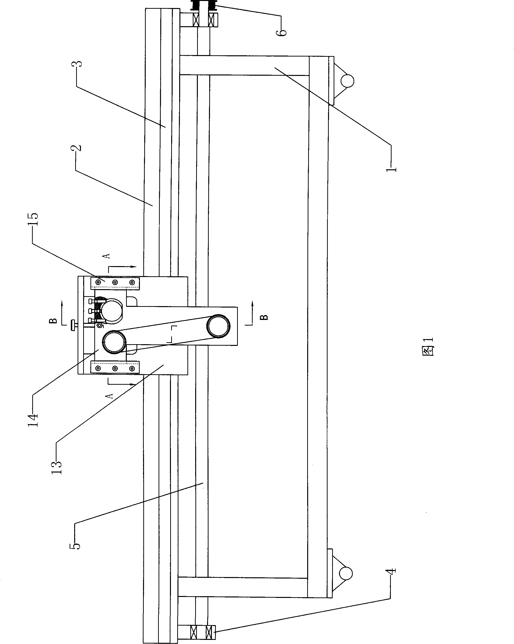
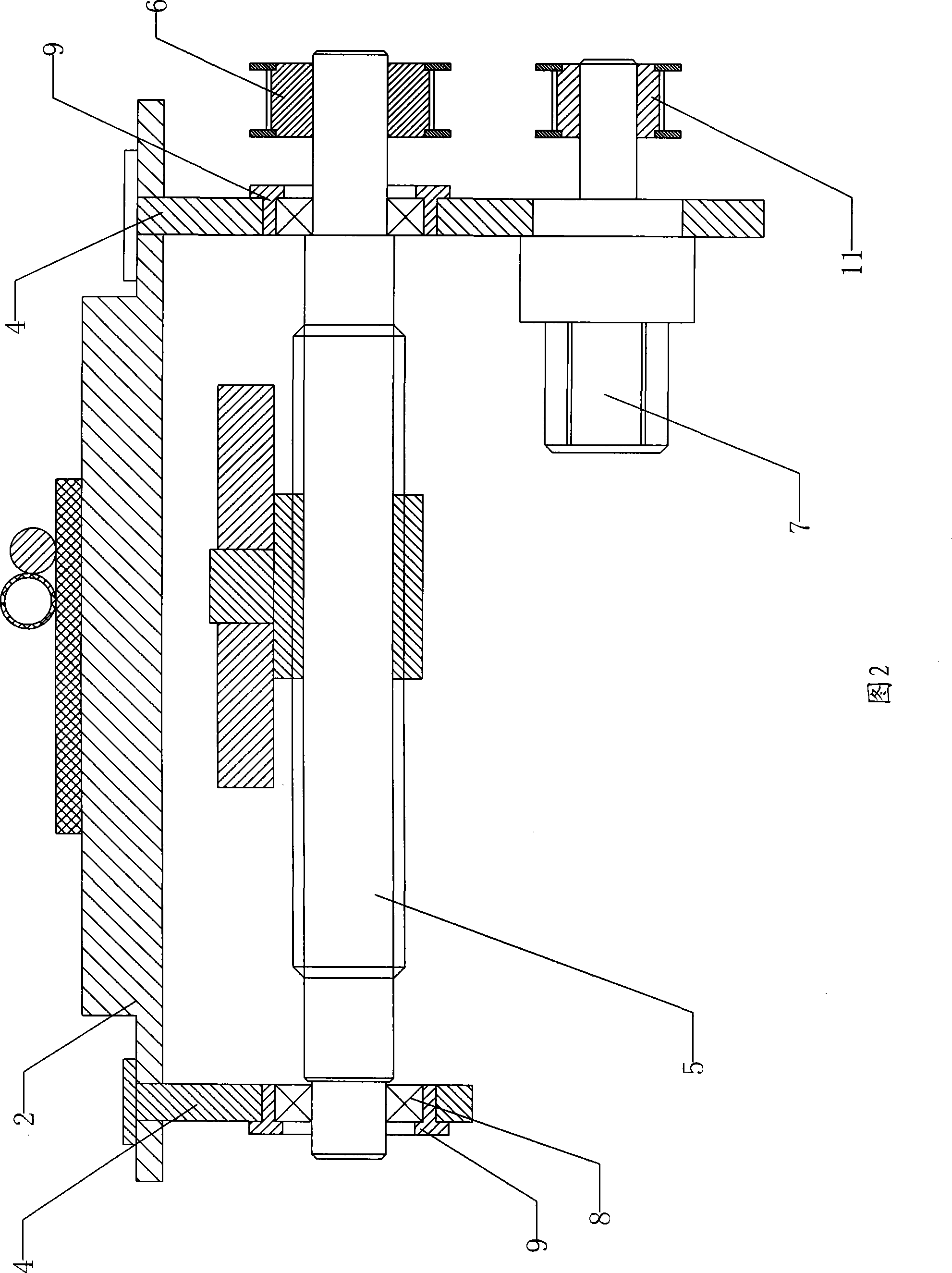
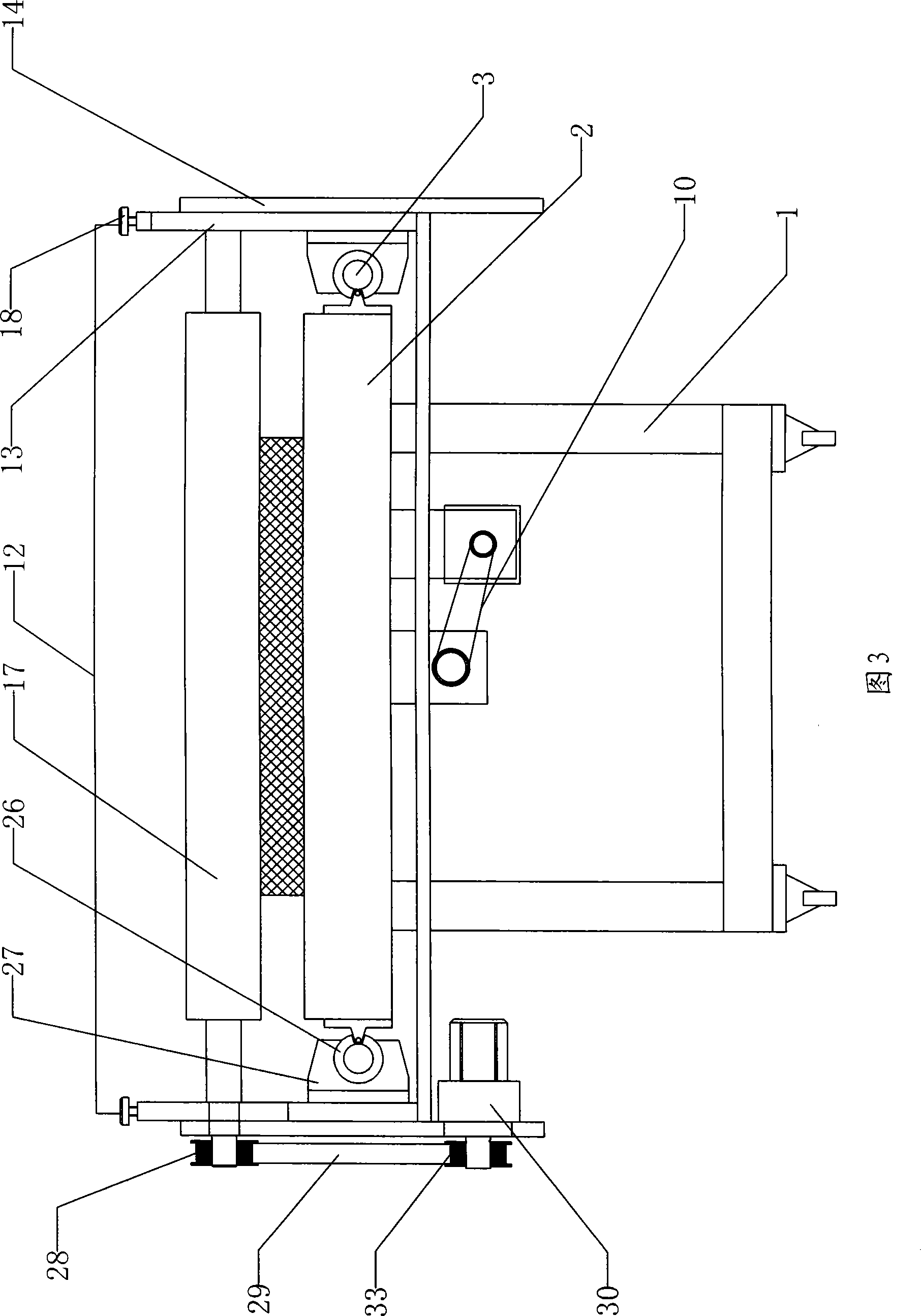

Image

  • Novel film applicator
  • Novel film applicator
  • Novel film applicator

Examples


Embodiment Construction

[0020] Such as Figure 1-3 As shown, the novel film coating machine described in the embodiment of the present invention includes a frame 1, a workbench 2, a guide rail 3, a hanging plate 4, a lead screw 5 and a motor 7, the upper part of the frame 1 fixes the workbench 2, and the workbench 2 There are guide rails 3 on both sides, hanging boards 4 are hung on both ends of the workbench 2, and the two hanging boards 4 are connected to both ends of the screw 5 through bearings 8, bearing sleeves 9 are placed outside the bearings 8, and the right end of the screw 5 is connected to the pulley 6 The right hanging plate 4 bottom is fixed motor 7, and the pulley 11 that connects on the motor 7 axles connects the belt pulley 6 of leading screw 5 right ends by synchronous belt 10, and motor 7 can drive leading screw 5 to rotate by synchronous belt 10 after starting the machine, leading screw 5 sleeves in the silk mother 25 of film coating device 12 bottoms.

[0021] Such as Figure 3...


PUM


Abstract

The invention relates to a novel film coating machine, comprising a machine frame, a work-table, two guide rails, two hanging plates, a lead screw and an electric motor. The work-table is fixed on the machine frame; the guide rails are respectively arranged on both sides of the work-table, and the hanging plates are arranged at both ends of the work-table; the two hanging plates are connected with the two ends of by a bearing; a bearing housing is coated on the bearing, and the right end of the lead screw is connected with a belt wheel; the electric motor is fixed on the lower part of the right hanging plate, the belt wheel on the electric motor is connected with the belt wheel arranged at the right end of the lead screw, and the lead screw is coated in the nut; the film costing device comprises a riser, a slider, a fixing guide rail, an optical axis, a rubber shaft, frame strips, a connect plate, a nut, a linear bearing and an electric motor. The invention has the advantages of that the picture is fixed, the method that the rubber shaft moves horizontally and rolls for film coating in the inverse direction is adopted; the stability of film costing is enhanced and the film coatingquality is improved; the gap between the rubber shaft, the movement speed of the rubber shaft and the rolling speed is adjustable; the film coating quality is ensured and the thickness of the film coat is controlled.

Description

technical field [0001] The invention relates to a novel coating machine. Background technique [0002] Existing film coating equipment mainly includes rubber shafts, worktables, etc. During processing, the picture is fixed flat on the workbench, and the movement of the worktable drives the picture to pass through the rubber shaft on the upper part of the film coating equipment, so that The paint is covered on the surface of the picture to complete the film coating; during the film coating process, the glue shaft rolls synchronously with the movement of the picture, and the paint on the glue shaft is continuously replenished. However, there are serious defects in this common film coating method. Since the rubber shaft is passively rolled along with the movement of the picture during film coating, the uniformity of the film coating and the firmness of the adhesion are relatively poor, which affects the overall coating of the picture. Film quality; and this coating method can ...

Claims


Application Information

Patent Timeline
Patent Type & Authority Patents(China)
IPC IPC(8): B05C1/12B05C13/02
Inventor 常明旺
Owner 常明旺
Learn More