Cabinet combination method of optical fiber distribution cabinet and optical fiber distribution cabinet capable of cabinets combination and expansion

A distribution cabinet and optical fiber technology, applied in the coupling of optical waveguides, etc., can solve the problems of small optical fiber distribution capacity, no compatible mechanism between cabinets, affecting the operation and maintenance of splicing lines, etc., to achieve convenient operation and maintenance, safe and reliable fixation , to meet the effect of large capacity

Inactive Publication Date: 2010-05-19
昆山市大唐通讯设备有限公司
View PDF6 Cites 0 Cited by
  • Summary
  • Abstract
  • Description
  • Claims
  • Application Information

AI Technical Summary

Problems solved by technology

The current optical fiber distribution cabinet is routed in the front of the cabinet or wound on the structure on both sides of the front, so its optical fiber distribution capacity is not large, and the routing in the front also affects the operation and maintenance of the splicing line. The structure of each fiber distribution cabinet is independent, and there is no compatible mechanism between cabinets, so it is difficult to connect and expand the fiber distribution cabinet
Insufficient capacity of existing optical fiber distribution equipment will affect the advancement of my country's 3G projects

Method used


Image

  • Cabinet combination method of optical fiber distribution cabinet and optical fiber distribution cabinet capable of cabinets combination and expansion
  • Cabinet combination method of optical fiber distribution cabinet and optical fiber distribution cabinet capable of cabinets combination and expansion
  • Cabinet combination method of optical fiber distribution cabinet and optical fiber distribution cabinet capable of cabinets combination and expansion

Examples


Embodiment Construction

[0026] The specific implementation of the optical fiber distribution cabinet capable of combining cabinets and expanding the capacity of the present invention will be given below with reference to the accompanying drawings.

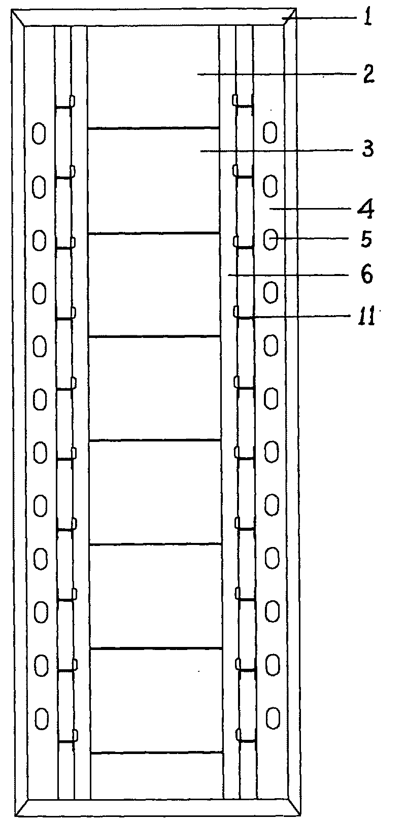
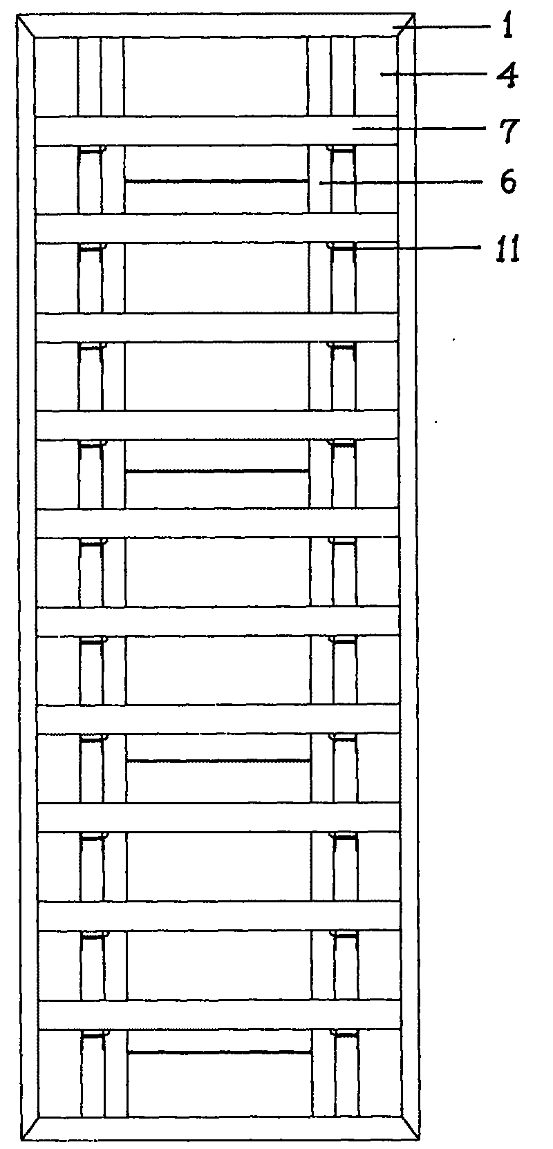
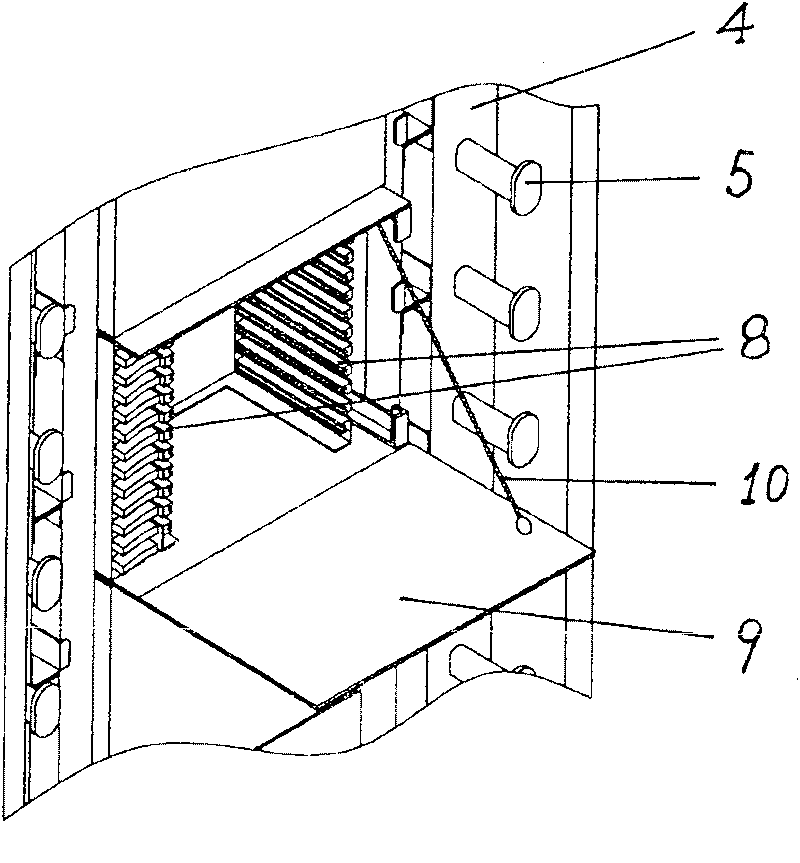
[0027] See attached figure 1 . The optical fiber distribution cabinet that can be combined and expanded in the present invention includes a frame 1, a lead cable frame 2, an integrated frame 3, a winding frame 4, a winding reel 5, a support frame 6, and a frame door, a side door, and a rear door (in the figure not shown).

[0028] Rack 1 is composed of a 19-inch standard rack, which is made of steel and aluminum. The base of the rack is made of high-quality cold-rolled plate, which makes the rack more stable and firm. Hinge connectors are connected to both ends of frame 1, side doors are connected to both sides of frame 1 through plug-in movable connectors, and rear doors are connected to the back of frame 1 through detachable hinge connectors; all door...


PUM


Abstract

The invention relates an optical-fiber distribution cabinet combing method which is realized as following: a horizontal trough and a connecting extension end extending toward the cabinet side are arranged in an optical distribution cabinet comprising a frame, a wiring frame, an integrating frame, a winding frame, a winding plate and a support frame; when a movable side door is disassembled, the optical fiber distribution cabinet can be combined with the same cabinet on both the left side and the right side. The horizontal trough used for combining cabinets and expanding capacity for the optical fiber distribution cabinet is composed of a support bar, a T-shaped trough, a trough plate and an expanding connection end and arranged at the back of the frame. The expanding connection end is a trough structure extending to a proximal side door. The invention has the following beneficial effects that the cabinet combination and capacity expanding can be carried out time after time to meet thehigh capacity requirement to the optical fiber distribution cabinet; adopting the back wiring apparatus can largely store the redundant jumper; adopting the guide-rail welding wiring integration modeleads the capacity expanding and mounting to be more flexible; the structure is proper and the operation and maintenance are convenient; a cable accessing unit is arranged to lead the cable accessing,grounding and fixing to be safe and reliable.

Description

【Technical field】 [0001] The invention relates to the technical field of post and telecommunications equipment, in particular to a method for merging optical fiber distribution cabinets and an optical fiber distribution cabinet that can be combined and expanded. 【Background technique】 [0002] An information society cannot do without communication equipment. In the urban communication network, more and more optical fibers are used, therefore, the use of optical fiber distribution equipment is also increasing, and the requirements are getting higher and higher. Optical fiber distribution equipment is an interface terminal equipment used for connection, splicing and line adjustment between the backbone optical cable and optical terminal in the optical fiber network, and realizes the fixing, splitting, grounding protection of optical cables, and the fusion, distribution, coiling and scheduling of optical fibers. The current optical fiber distribution cabinet is routed in the f...

Claims


Application Information

Patent Timeline
Patent Type & Authority Patents(China)
IPC IPC(8): G02B6/38
Inventor 蔡志祥
Owner 昆山市大唐通讯设备有限公司
Why Eureka
Try Eureka