Supercharge Your Innovation With Domain-Expert AI Agents!

Scintillator panel and radiation detector

A scintillation screen and radiation technology, applied in the field of scintillation screens, can solve the problems of easy scattering of visible light, scattering of visible light entering a protective film, deterioration of image resolution characteristics, etc.

Inactive Publication Date: 2009-01-14
KK TOSHIBA +1
View PDF2 Cites 10 Cited by
  • Summary
  • Abstract
  • Description
  • Claims
  • Application Information

AI Technical Summary

Problems solved by technology

However, there is a problem that the visible light incident on the protective film is scattered, resulting in deterioration of image resolution characteristics.
Therefore, visible light incident on the protective film tends to be scattered, and as a result, there is a problem that image resolution characteristics deteriorate

Method used


Image

  • Scintillator panel and radiation detector
  • Scintillator panel and radiation detector
  • Scintillator panel and radiation detector

Examples


Embodiment Construction

[0026] Hereinafter, embodiments of the present invention will be described with reference to the drawings.

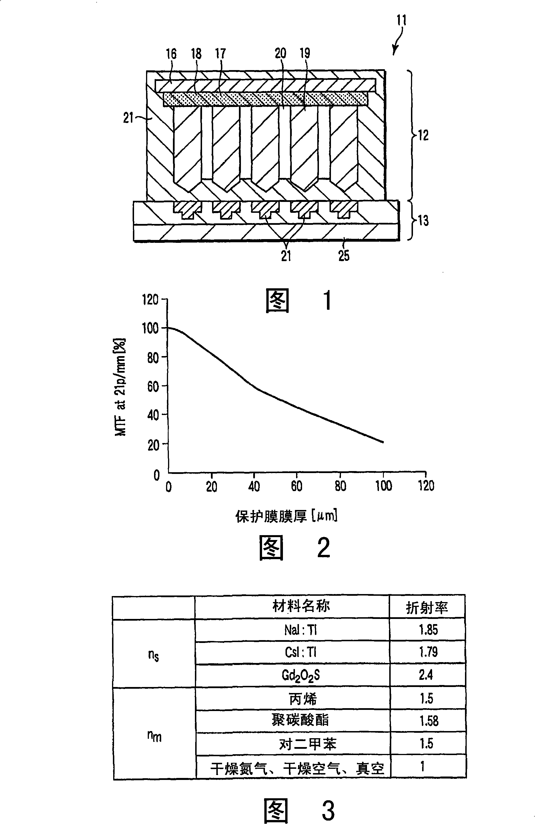
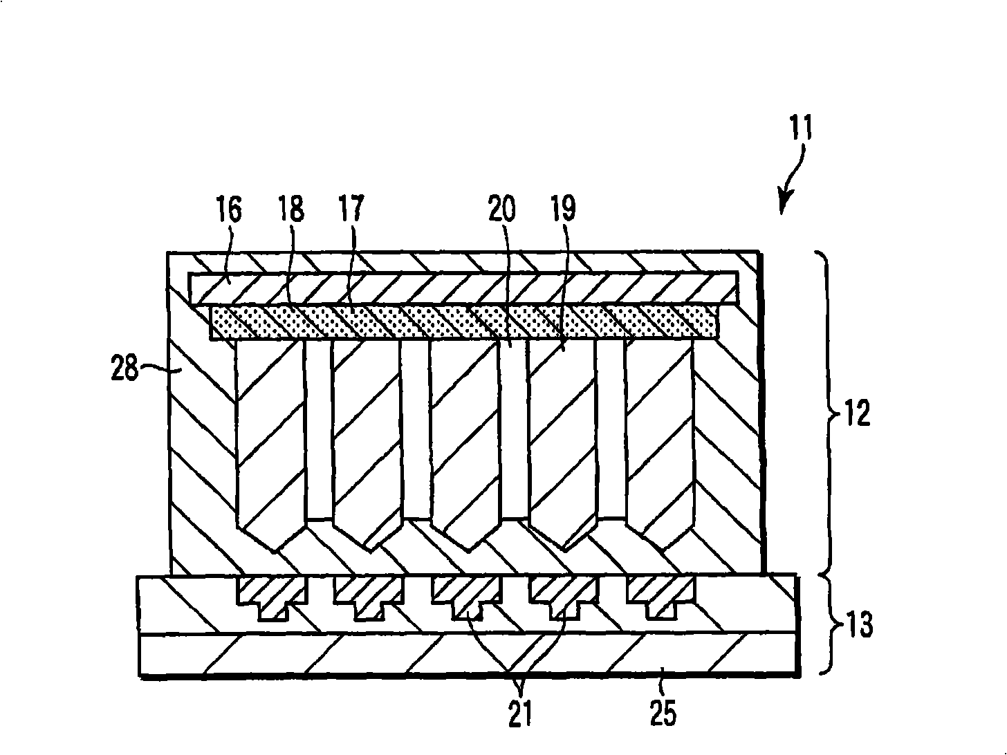
[0027] Figure 1 to Figure 4 Embodiment 1 is shown.

[0028] As shown in FIG. 1 , the radiation detector 11 includes a scintillation screen 12 and a photoelectric conversion element 13 .

[0029] The scintillation screen 12 has a radiation-permeable support base 16 formed by curing carbon fibers with resin, and a light-reflecting material dispersion film 17 is formed on the surface of the support base 16 in a planar shape. The light-reflecting material dispersion film 17 is made of, for example, an organic material such as p-xylene. Light reflective material particles 18 of an inorganic material are dispersed in this light reflective material dispersion film 17 . Therefore, this light reflective material dispersion film 17 also functions as a light reflective film.

[0030] A scintillation layer 19 capable of converting incident radiation into visible light is formed...


PUM

PropertyMeasurementUnit
diameteraaaaaaaaaa
refractive indexaaaaaaaaaa

Abstract

A scintillator panel comprises a support base plate (16) through which radiation can pass, a light-reflective material dispersion film (17) which is provided flatly on the support base plate and in which light-reflective material particles (18) for reflecting visible light are dispersed, and a scintillator layer (19) for converting incident radiation into visible light is provided on the light-reflective material dispersion film.

Description

technical field [0001] The present invention relates to a scintillation screen for converting radiation into visible light, and a radiation detector using the scintillation screen. Background technique [0002] As a new generation of detectors for X-ray diagnosis, planar detectors using active matrices are being developed. Such a planar detector detects irradiated X-rays, and outputs X-ray images or real-time X-ray images as digital signals. Furthermore, in this planar detector, X-rays are converted into visible light or fluorescence by using a scintillation layer, and this fluorescence is converted into The signal charge is used to obtain an image. [0003] Materials commonly used as the scintillation layer usually include cesium iodide (CsI): sodium (Na), cesium iodide (CsI): thallium (Tl), sodium iodide (NaI), or gadolinium oxysulfide (Gd 2 o 2 S) etc. Image resolution characteristics can be improved by forming grooves on the scintillation layer by dicing or the like...

Claims


Application Information

Patent Timeline
Patent Type & Authority Applications(China)
IPC IPC(8): G01T1/20G21K4/00C09K11/00
CPCC09K11/616G01T1/20G21K4/00G01T1/2002C09K11/7701
Inventor 若松俊辅
Owner KK TOSHIBA
Features
  • R&D
  • Intellectual Property
  • Life Sciences
  • Materials
  • Tech Scout
  • Unparalleled Data Quality
  • Higher Quality Content
  • 60% Fewer Hallucinations
Learn More