
Double-air sac structure of vibration moulding machine

A technology of vibration molding machine and double airbag, applied in ceramic molding machines, material molding presses, presses, etc., can solve the problem of anode block dummy specific gravity value lagging behind the development of electrolytic aluminum process, difficult to guarantee anode block quality, and heavy hammer vibration. It is not easy to balance and other problems, so as to shorten the maintenance cycle, reduce the leakage point and failure rate, and increase the false specific gravity.

Inactive Publication Date: 2009-01-21
GUIZHOU BRANCH CHINA ALUMINUM IND
View PDF0 Cites 8 Cited by
  • Summary
  • Abstract
  • Description
  • Claims
  • Application Information

AI Technical Summary

Problems solved by technology

[0003] The traditional molding process relies on the weight of the hammer to apply pressure combined with vibration to press the paste into shape. The false specific gravity value of the anode block produced lags behind the development of the electrolytic aluminum process.
The existing vibration molding machines of domestic carbon manufacturers basically adopt the traditional molding process, and the quality of the anode block is not easy to guarantee
Some foreign manufacturers have improved the vibration molding machine. The vibration molding machine is designed with a heavy hammer single air bag pre-compression structure, so the pre-pressure on the paste is increased, and the pre-compression performance of the vibration molding machine is improved; The vibration is not easy to balance, and the pressure is uneven; the lifting shaft passes through the middle of the airbag, and the airbag is a dynamic seal, so the air pressure is easy to leak; and the airbag is connected to the upper cover and the lower hammer, which is extremely inconvenient to disassemble and assemble, and the maintenance work is intensive.

Method used


Image

  • Double-air sac structure of vibration moulding machine
  • Double-air sac structure of vibration moulding machine

Examples


Embodiment Construction

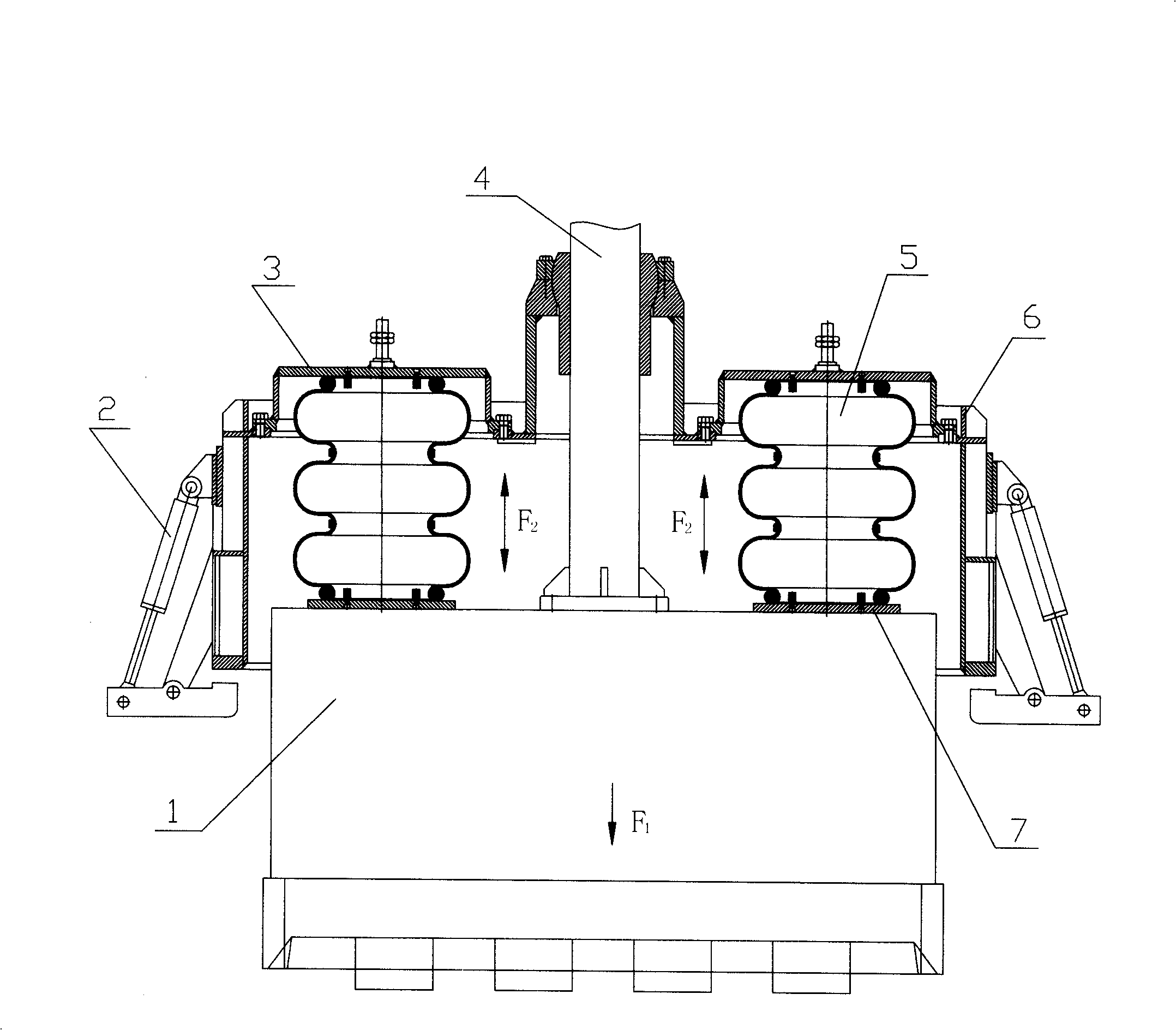
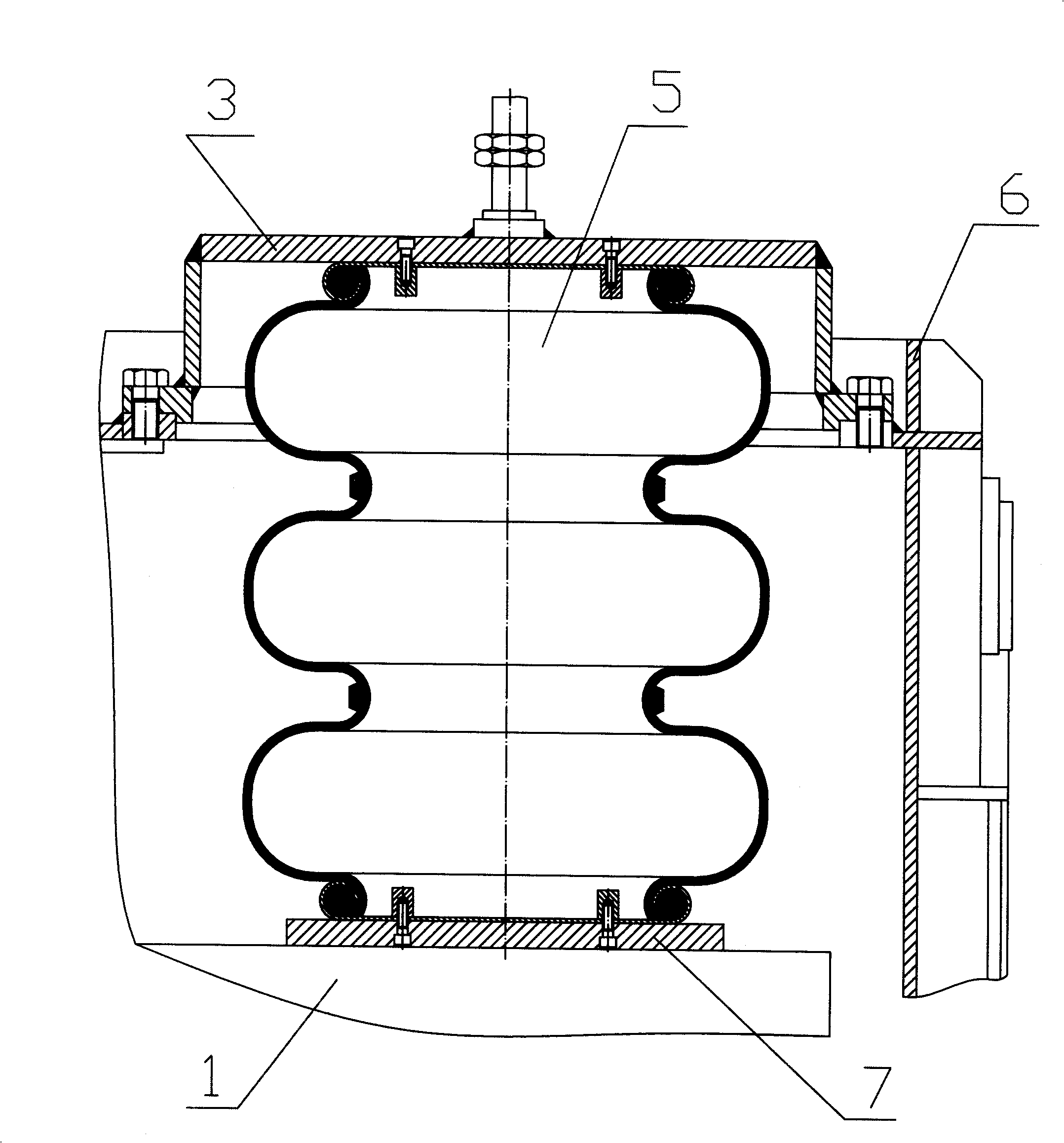
[0017] Embodiment of the present invention: the double-airbag structure of the vibration molding machine includes components such as a weight and a weight lifting shaft. A cover 6 is arranged above the weight 1, and the weight lifting shaft 4 passes through the cover 6 from the middle; A lower pedal 7 is arranged on the hammer 1, and two airbags 5 are installed in the cover body 6, so that the two airbags 5 are respectively on both sides of the lifting shaft 4 of the weight, and are located between the airbag cover plate 5 and the lower pedal 7, and the airbag cover The plate 5 is connected with the cover body 6 by bolts, the airbag seat on the top of the airbag is also connected with the airbag cover plate 5 by bolts, the airbag seat at the lower part of the airbag is connected with the lower pedal 7 by bolts, and the airbag 5 together with the lower pedal 7 is naturally placed on the weight 1 On the plane, there is no need to fix it, and the form of floating contact is adopte...


PUM


Abstract

The invention discloses a double-balloon structure for vibration forming machine. A cover body (6) is arranged above a heavy punch (1). A shifting shaft for heavy punch passes through the middle of the cover body (6). A lower pedal (7) is arranged on the top of the heavy punch (1). Two gasbags (5) are arranged between a gasbag housing plate (3) and the lower pedal (7) and are respectively positioned at the two sides of the shifting shaft of the heavy punch. The two lateral parts of the cover body (6) are provided with two groups of hydro cylinders; wherein, the gasbag housing plate (3) is connected with the cover body (6) by a bolt; a gasbag seat arranged at the upper part of the gasbag is connected with the cover body (6) by a bolt, and the gasbag seat arranged at the lower part of the gasbag is connected with the lower pedal (7) by a bolt; the gasbag seat arranged at the lower part of the gas airbag and the lower pedal are in floating contact with the upper plane surface of the heavy punch. The double-balloon structure can increase the bulk specific weight of an anode forming block, ensure the uniform density of the anode, greatly improve the quality of the anode forming block, increase conductivity, and reduces the unit cost of electrolytic aluminum; the gasbags have extremely convenient disassembly, with the overhaul cycle shortened.

Description

technical field [0001] The invention relates to a vibration forming machine for carbon production. Background technique [0002] The function of the vibration molding machine for carbon production is to vibrate the kneaded material into an anode carbon block through a heavy hammer and a mold. It is one of the key equipment for the production of electrolytic aluminum anodes. The compactness of the vibrating material determines the anode consumption cycle, and also directly affects the cost factors such as the power consumption of electrolytic aluminum. [0003] The traditional molding process is to press the paste by the weight of the hammer combined with vibration, and the false specific gravity value of the anode block produced lags behind the development of the electrolytic aluminum process. The existing vibration molding machines of domestic carbon manufacturers basically adopt the traditional molding process, and the quality of the anode block is not easy to guarantee. ...

Claims


Application Information

Patent Timeline
IPC IPC(8): B28B1/087
CPCB30B11/022
Inventor 陈长声张衡曾垂新姜新立周耘张支君佘建敏李强张怀成张云贵张鸿鸣刘芾
Owner GUIZHOU BRANCH CHINA ALUMINUM IND
Learn More