Double-helix shaft double-helical ribbon concrete mixing plant

A mixing device and concrete technology, which is applied in the direction of cement mixing device, clay preparation device, chemical instrument and method, etc., can solve the problems that concrete is not easy to cling to a shaft, concrete is easy to clot and agglomerate, and material flow is not smooth, etc., to achieve Wide range of use, improved mixing efficiency, and reduced cleaning time

Inactive Publication Date: 2010-07-07
蔡达棋
View PDF1 Cites 0 Cited by
  • Summary
  • Abstract
  • Description
  • Claims
  • Application Information

AI Technical Summary

Problems solved by technology

[0005] The purpose of the present invention is to solve the problems existing in the existing concrete mixer that the materials flow in the mixer is not smooth, the concrete is easy to cling to the shaft and agglomerate, the mixing efficiency is low, and the energy consumption is large, etc. Larger, the material flows more smoothly in the mixer, the concrete is not easy to hold the shaft and agglomerate, the mixing is more efficient, and the double helix shaft and double ribbon concrete mixing device with lower energy consumption

Method used


Image

  • Double-helix shaft double-helical ribbon concrete mixing plant
  • Double-helix shaft double-helical ribbon concrete mixing plant
  • Double-helix shaft double-helical ribbon concrete mixing plant

Examples


Embodiment Construction

[0025] The following embodiments will further illustrate the present invention in conjunction with the accompanying drawings.

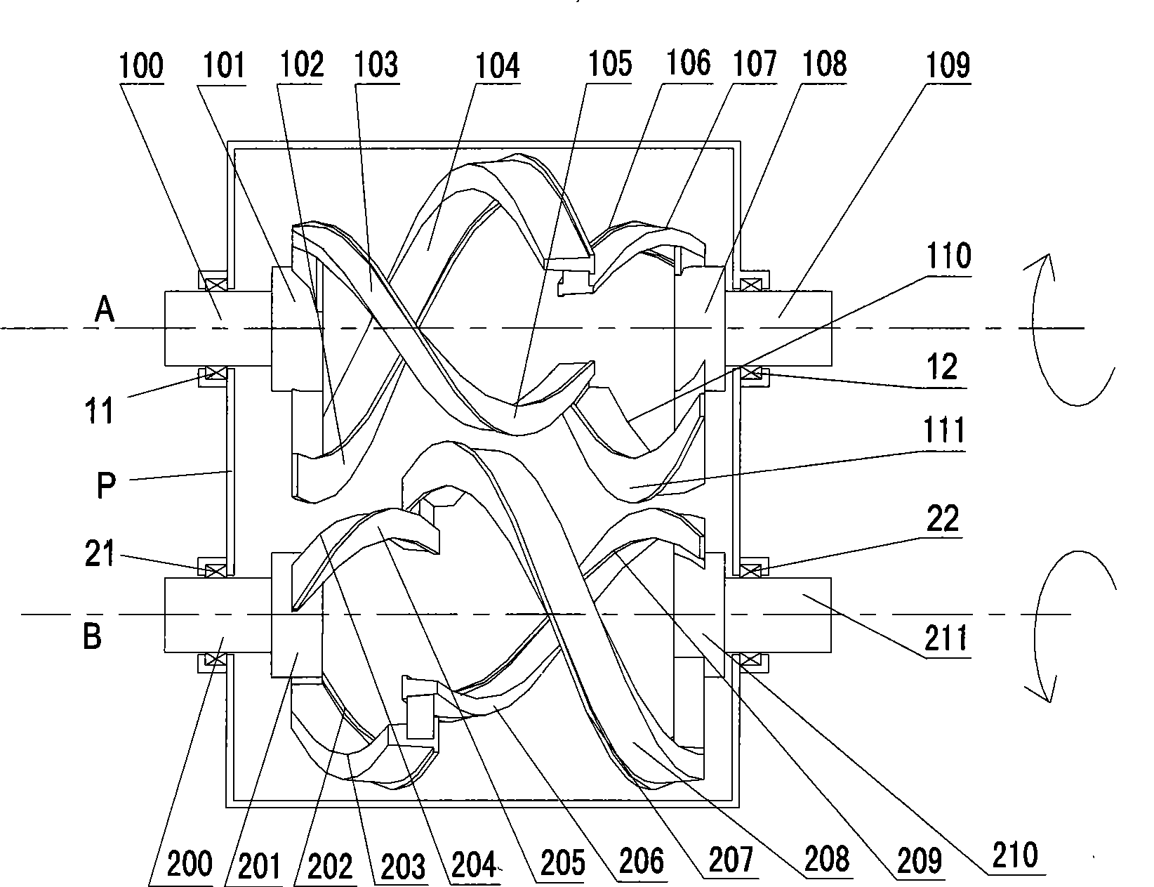
[0026] see image 3 , the present invention is provided with a body P, a first stirring system A and a second stirring system B.

[0027] The first stirring system A is provided with a left shaft head 100, a right shaft head 109 and 4 screw shafts, and the 4 screw shafts include an inner return unit shaft 107, an outer return unit shaft 110, an outer feed unit shaft 104 and an inner feed unit The shaft 103, the left end of the outer feed unit shaft 104 and the left end of the inner feed unit shaft 105 are respectively connected with the left spindle head 100, the right end of the outer feed unit shaft 104 is connected with the left end of the inner return unit shaft 107, and the inner return unit shaft The right end of 107 is connected with the right shaft head 109, the right end of the inner feed unit shaft 103 is connected with the left end of the ...


PUM


Abstract

The invention relates to a double spiral axis double spiral ribbon concrete mixing plant, which relates to a mixer for clay or cement and other materials which turns around the horizontal or basically horizontal axis. The concrete mixing plant is provided with a machine body, a first agitation system and a second agitation system. The fist agitation system is provided with a left spindle head, a right spindle head and four spiral axes which are connected with the left and right spindle heads. The second agitation system is provided with the left spindle head, the right spindle and the four spiral axes which are connected with the left and right spindle heads. The direction of the spiral of an internal return unit shaft is opposite to that of the spiral of an internal feeding unit shaft; and the direction of the spiral of an external feeding unit shaft is opposite to that of the spiral of the external return unit shaft. The left and right spindle heads of the first agitation system andthe second agitation system are connected with a bearing bracket arranged on the machine body. The speed at which the spindle axes move relative to materials is larger;, so the materials are subject to smaller resistance when being mixed in the mixer, the cement is difficult to curdle around the axes, and the materials flow smoothly in the mixer, thus ensuring that the mixer has .lower energy consumption and higher mixing efficiency, reducing cleaning time and increasing the service efficiency of the mixer.

Description

technical field [0001] The present invention relates to a mixer for clay or cement and other materials having a horizontal or substantially horizontal axis. Background technique [0002] Concrete mixing equipment is an important equipment in the construction of construction projects. Generally, mixing equipment that operates around a horizontal or basically horizontal axis is used. Most of the existing concrete mixing equipment adopts twin-shaft mixers (see figure 1 ), its structure includes: a mixer body, two parallel mixer shafts 3a, 3b horizontally arranged in the mixer body and feeding, stirring and returning units 31-33 arranged on the mixer shaft, each unit includes The stirring arm and the blades connected to the stirring arm. Since each unit is discrete, the stirring of the material in the mixer is realized by the individual shoveling of a single blade, so the material cannot produce an overall continuous circulation flow. Using the existing twin-shaft mixer, the ...

Claims


Application Information

Patent Timeline
Patent Type & Authority Patents(China)
IPC IPC(8): B28C5/14
Inventor 黄建军
Owner 蔡达棋
Why Eureka
Try Eureka