

Clutch type electric screw press
An electric screw and clutch technology, which is applied in the direction of presses, stamping machines, manufacturing tools, etc., can solve the problems of low service life, difficulty in replacement, and increased cost of lubricating oil conditions, and achieves strong reliability and safety, and process adaptability The effect of wide range and long service life
Inactive Publication Date: 2009-01-21
青岛益友锻压机械有限公司
View PDF0 Cites 7 Cited by
- Summary
- Abstract
- Description
- Claims
- Application Information
AI Technical Summary
Problems solved by technology
It can be seen from the transmission mode that when the screw and the nut are struck downward, the return stroke of the slider ends, and the whole process of the slider staying at the top dead center is in contact with the upper surface of the screw tooth surface, the lubrication condition is very poor, and the lubricating oil The condition of the flywheel is very high, which leads to an increase in the cost of use. Another problem is that the service life of the large flywheel is too large and the speed is high, so it is difficult to replace
Method used
View moreImage
Smart ImageViewing Examples

Examples
Embodiment Construction
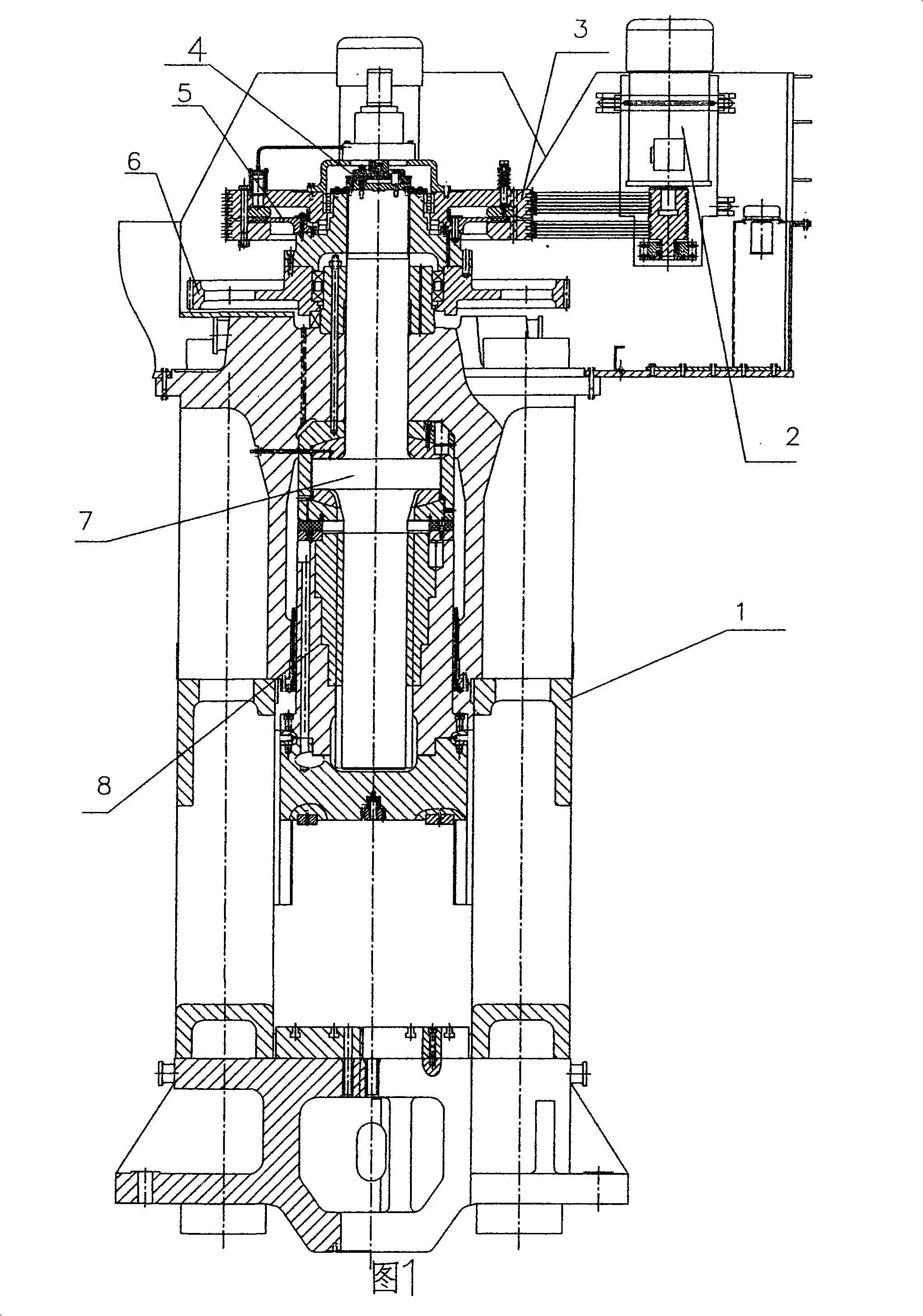
[0012] In Fig. 1, the clutch-type electric screw press of the present invention includes a frame 1, a drive motor 2 installed above the frame, a clutch flywheel 3 driven by the drive motor, and a clutch 4 installed on the clutch flywheel. After the clutch is engaged The friction disc 5 that drives it to rotate, is fixed together with the friction disc and is driven by the electric motor 6, the screw rod 7 fixed on the electric flywheel, and the slide block 8 with internal thread installed on the bottom of the screw rod.
Login to View More PUM
 Abstract
The invention relates to a clutch-type electric screw press which comprises a frame, a driving motor which is arranged above the frame, a clutch flywheel which is driven by the driving motor, a clutch which is arranged on the clutch flywheel, a friction disc which can drive the clutch to rotate after the clutch is jointed, an electric flywheel which is fixed with the friction disc and which is driven by the motor, a screw rod which is fixed on the electric flywheel and a slide block which is arranged at the lower part of the screw rod and which is provided with an internal thread. The clutch-type electric screw press of the invention has large capacity, wide technical adaptation range, strong reliability and safety, long service life and low total power of the motor and can be widely applied in the pressure shaping technique.
Description
[0001] Technical field The present invention relates to a clutch-type electric screw press, which can be widely used in press forming processes. Background technique [0002] Existing electric screw presses generally adopt a motor to drive the flywheel and the screw to rotate through a belt or a gear, and drive the slide block to strike through the screw pair. Due to the small transmission ratio and short stroke, this structure cannot meet the high energy demand of the screw press. Another type of screw press adopts the direct drive type, that is, the flywheel and the motor rotor are integrated, and the stator is fixed on the top surface of the upper beam. This structure reduces the transmission chain to the shortest, but there is still the problem of insufficient input energy, and the cost is expensive. Defects such as large starting current. There is also a clutch type screw press, which is driven by the main motor through the belt to make the large flywheel rotate continuo...
Claims
Login to View More Application Information
Patent Timeline
 IPC IPC(8): B30B1/22B30B15/12
CPCB30B1/188
Inventor韩林元
Owner青岛益友锻压机械有限公司