
Plasma display panel and manufacturing method thereof

A display panel and plasma technology, applied in the direction of AC plasma display panels, cold cathode manufacturing, electrode system manufacturing, etc., can solve the problems of insufficient activation of getters, etc., and achieve the effect of improving poor display and low cost

Inactive Publication Date: 2009-01-21
HITACHI LTD +1
View PDF2 Cites 2 Cited by
  • Summary
  • Abstract
  • Description
  • Claims
  • Application Information

AI Technical Summary

Problems solved by technology

However, in such a structure, in order to stably obtain the effect of the getter, the arrangement method of the getter may require countermeasures such as insufficient activation of the getter.

Method used


Image

  • Plasma display panel and manufacturing method thereof
  • Plasma display panel and manufacturing method thereof
  • Plasma display panel and manufacturing method thereof

Examples


Embodiment Construction

[0035] Hereinafter, embodiments of the present invention will be described in detail based on the drawings. In addition, in all the drawings for describing the embodiments, in principle, the same reference numerals are assigned to the same parts, and repeated description thereof will be omitted.

[0036]

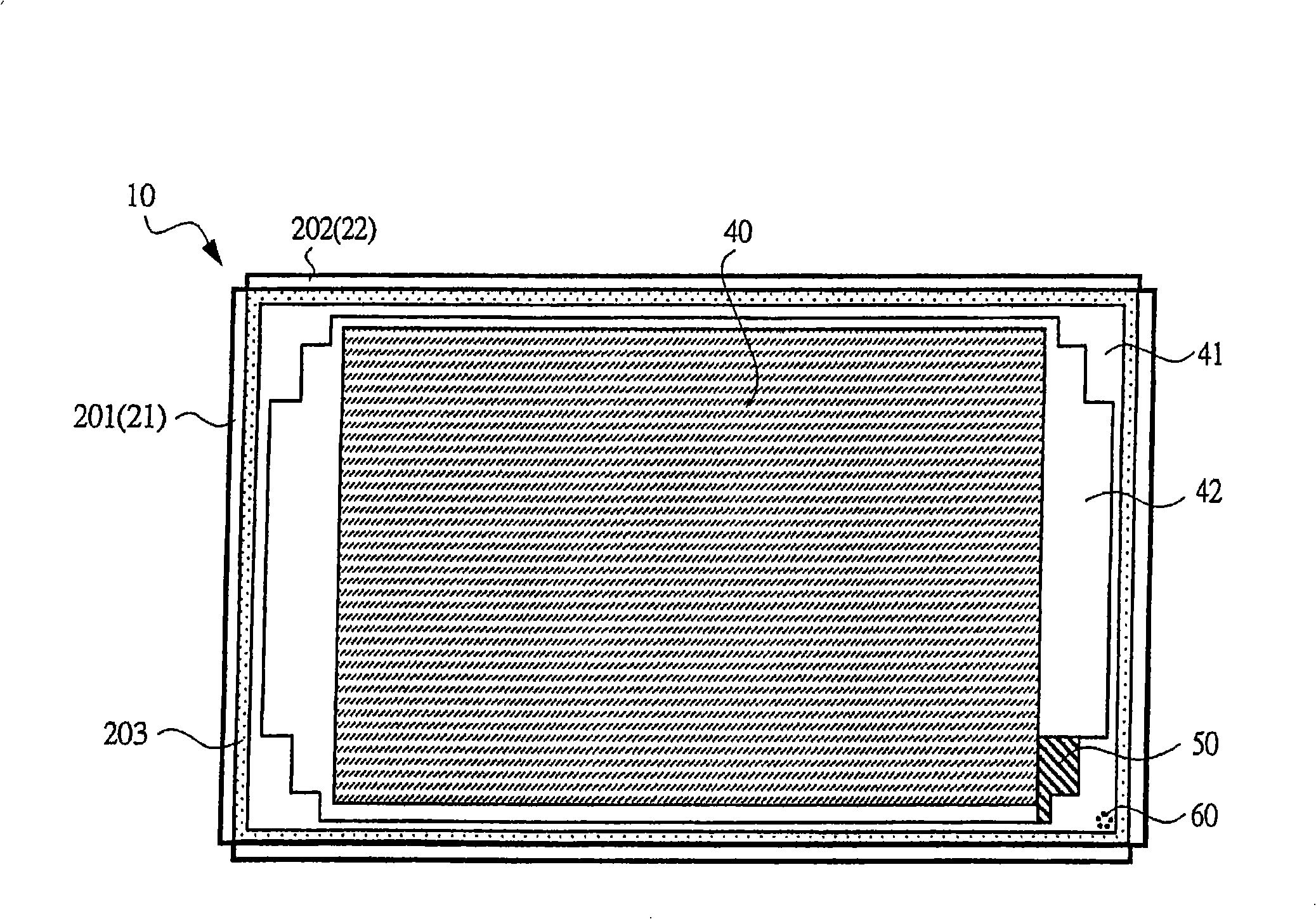
[0037] exist figure 1 In , the appearance of the PDP (first structural example) according to one embodiment of the present invention, that is, the planar structure viewed from the front side is shown. In this PDP (panel) 10, the first substrate (front glass substrate) 21 and the structure of the second substrate (rear glass substrate) 22 (the first substrate structure 201, the second substrate structure 202) are relatively combined. After the sealing region 203 is sealed with frit (sealing material), the interior of the panel (the region to be the discharge space) is evacuated through the vent hole 60, and the discharge gas is introduced to complete the sealing.

[0038]...


PUM


Abstract

A technology capable of preventing or suppressing a display defect in a PDP (detrimental effect due to local contamination of the display area caused by admixture of impurity gas at the time of introducing discharge gas) is provided. In a PDP, first barrier ribs and first phosphors formed between the first barrier ribs are provided so as to correspond to a display area. In a non-display area outside the display area, an air hole for evacuation from a discharge space and gas filling into the discharge space is provided in a part of an outer perimeter of the panel. Further, an area in which second phosphors having a property of absorbing impurity gas are formed is formed at a position between the display area and the air hole in a part of the non-display area, in particular, in a part of a dummy rib area.

Description

technical field [0001] The present invention relates to a plasma display panel (PDP), and more particularly to filling a discharge space with gas (discharge gas), phosphors, and the like. Background technique [0002] In the manufacture of conventional PDPs, it is an important factor to increase the purity of the discharge gas filled in the panel in order to stabilize the discharge characteristics and suppress the deterioration of the characteristics. Therefore, generally, in the discharge gas sealing process of the PDP, a method of sealing the discharge gas after removing impurity gas in the panel by heating while evacuating the inside of the panel is employed. [0003] However, in the above-mentioned method of enclosing the discharge gas, since the discharge gas is introduced through the vent hole and the core tube for exhausting the inside of the panel, the impure gas exhausted from the panel is adsorbed on the inner wall of the vacuum exhaust system, When the discharge ...

Claims


Application Information

Patent Timeline
Patent Type & Authority Applications(China)
IPC IPC(8): H01J17/49H01J17/04H01J9/00G09G3/28H01J11/12H01J11/22H01J11/24H01J11/26H01J11/34H01J11/42
CPCH01J11/52H01J9/38H01J11/12H01J11/42H01J11/34
Inventor 大平浩史村瀬友彦福井稔山本泰助
Owner HITACHI LTD
Learn More