
Junction box to be mounted on motor vehicle

A technology for motor vehicles and junction boxes, applied in the field of junction boxes, can solve problems such as the heat influence of internal circuit board relays, achieve the effects of reducing costs and assembly steps, preventing size increase, and increasing size

Inactive Publication Date: 2009-01-21
SUMITOMO WIRING SYST LTD
View PDF1 Cites 5 Cited by
  • Summary
  • Abstract
  • Description
  • Claims
  • Application Information

AI Technical Summary

Problems solved by technology

Since the thickness of the wires must be consistent on a single PCB, circuits with higher currents will require larger areas of wires, which prevents small board size reductions
[0009] Also, if a high-current relay having a large heat generation is housed in the case assembly as a board relay, since an internal circuit such as a bus bar, a printed circuit board, or the like is housed in the case assembly, and since it is thermally relatively weak The electrical and electronic components are mounted on the printed circuit board, so there is a problem that the internal circuit will be easily affected by the heat from the board relay

Method used


Image

  • Junction box to be mounted on motor vehicle
  • Junction box to be mounted on motor vehicle
  • Junction box to be mounted on motor vehicle

Examples


Embodiment Construction

[0035] now refer to Figures 1 to 7 , an embodiment of a junction box to be mounted on a motor vehicle according to the present application will be described in detail below.

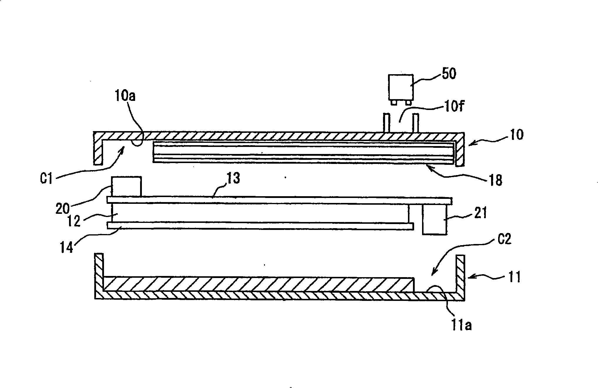
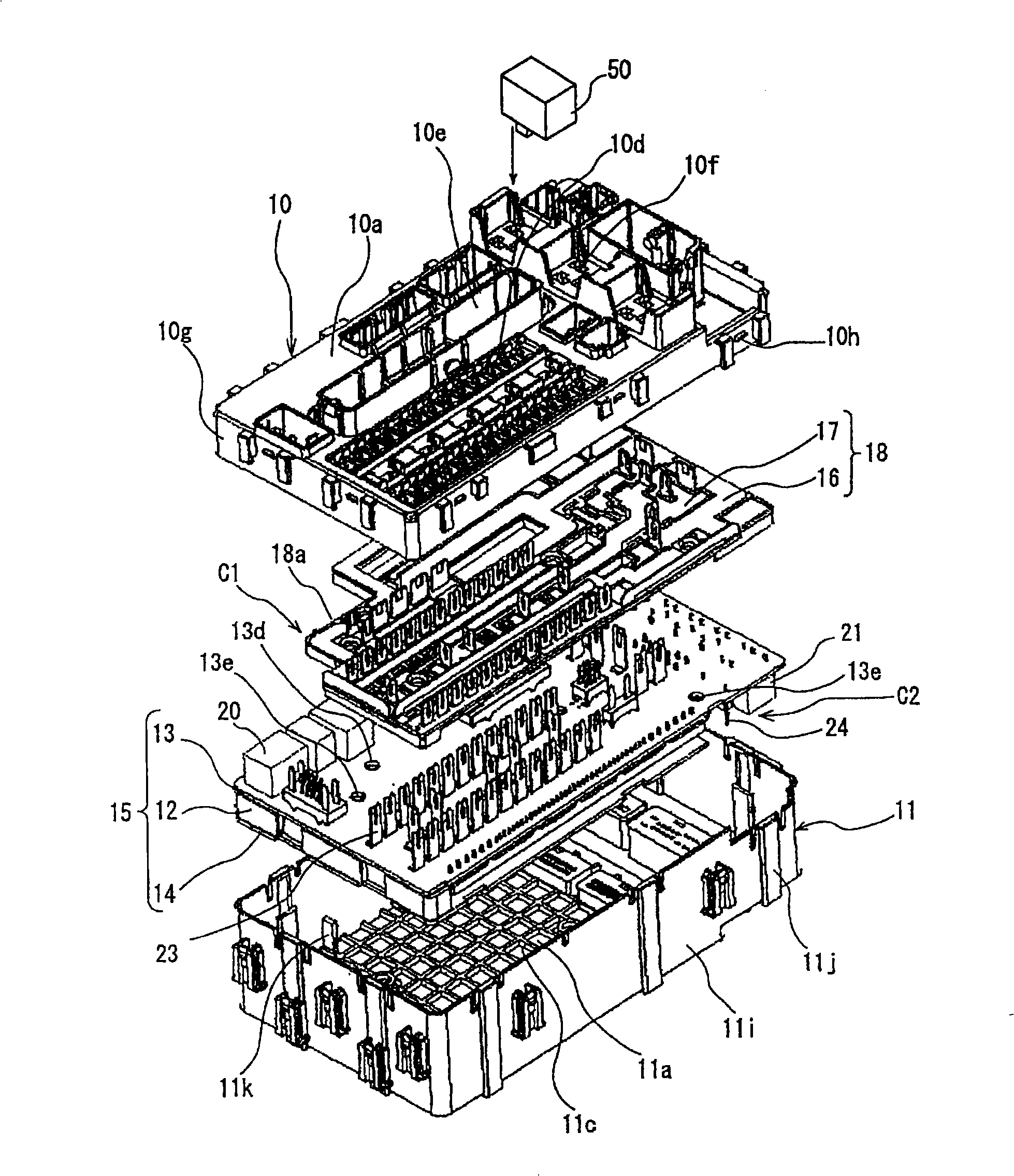
[0036] Such as figure 1 As shown in FIG. 3 , the junction box may include a housing assembly having an upper housing 10 and a lower housing 11 . The bus bar lamination unit 18 and the printed circuit board unit 15 are housed in the case assembly so that they are disposed from the upper case 10 to the lower case 11, and the bus bars 16 and insulating plates 17 are alternately laminated in the bus bar lamination unit, The printed circuit board unit includes a first printed circuit board 13 , a spacer 12 and a second printed circuit board 14 .

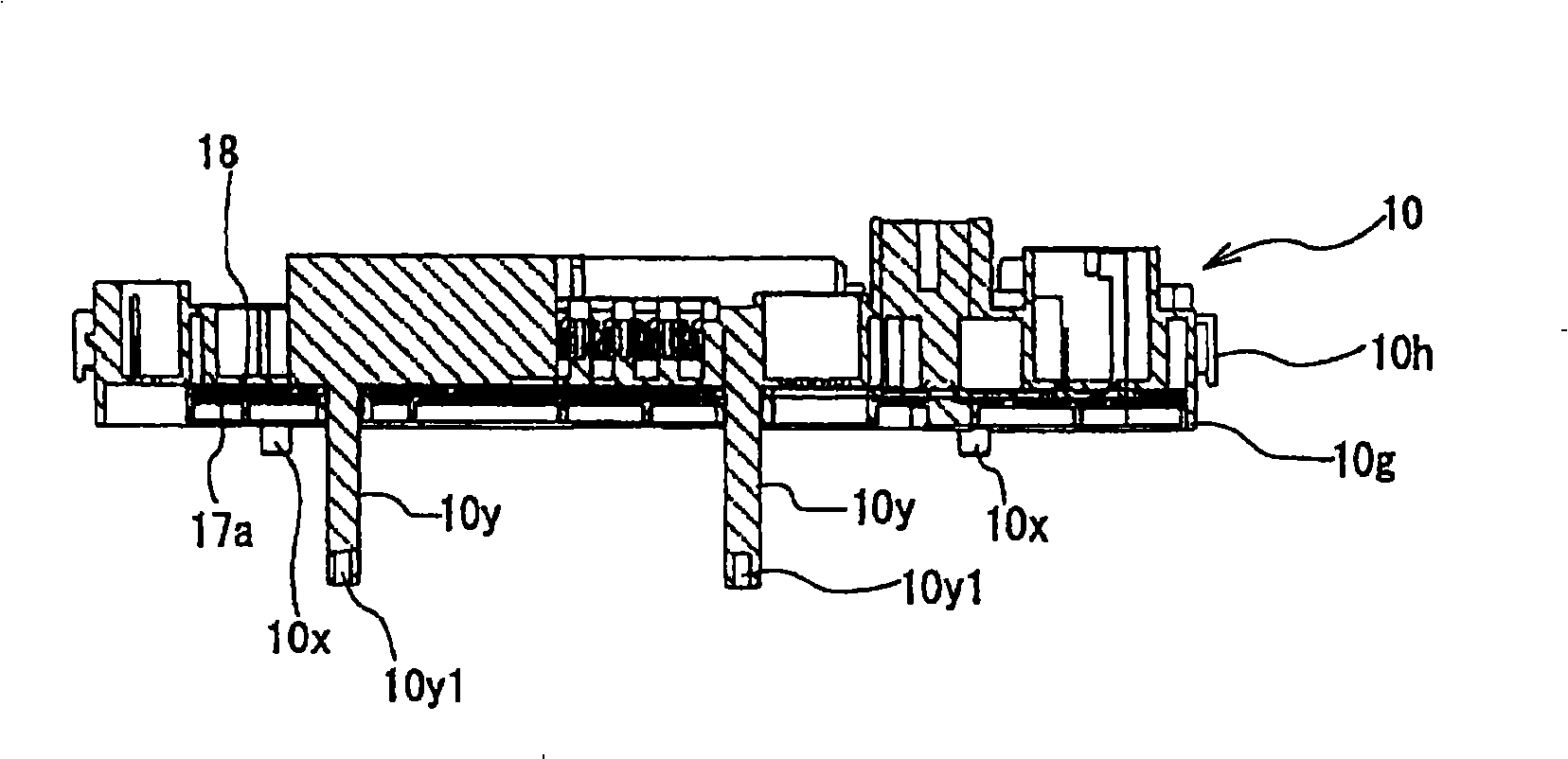
[0037] The fixing bar 10x having a shorter size may be integrally formed with the inner surface of the top wall 10a of the upper housing 10, and may extend downward from the inner surface. The shorter fixed rod 10x can penetrate through the busbar lamination un...


PUM


Abstract

The present invention relates to a junction box to be mounted on motor vehicle. The junction box has a casing assembly including an upper casing and a lower casing, a laminated unit including bus bars and insulation plates, and first and second printed circuit boards contained in the casing assembly. The first printed circuit board is used as a higher current circuit having thick-film conductors. The second printed circuit board is used as a middle or lower current circuit having thin-film conductors with thicknesses smaller than those of the thick-film conductors on the first printed circuit board. Board relays are mounted on a part of different peripheral portions on both sides of the first printed circuit board or a part of peripheral portion of either side of the first printed circuit board. The board relays are disposed in the casing assembly to be opposed to a first heat generating element containing space defined between a front side of the first printed circuit board and an inner surface of a top wall of the upper casing, and a second heat generating element containing space defined between a rear side of the first printed circuit board and an inner surface of a bottom wall of the lower casing.

Description

technical field [0001] The present application relates to a junction box to be mounted on a motor vehicle, and more particularly to a junction box which improves the connection position of a plurality of high-current relays which are large in size and are heating elements, thereby reducing wiring box size and take measures against heat generation. Background technique [0002] In connection with the rapid increase in the number of electrical and electronic components to be installed on motor vehicles, it may be required that a junction box mounted on a motor vehicle accommodate multiple printed circuit boards housing electrical and electronic components, as well as higher current relays together with Conventional common laminated unit for busbars and insulation boards. In particular, the higher-current relay, which is a heat-generating component, is inserted and connected to a relay accommodating area provided on the outside of the upper case or the lower case, in considera...

Claims


Application Information

Patent Timeline
IPC IPC(8): H02G3/16
CPCH05K7/026
Inventor 早川达也
Owner SUMITOMO WIRING SYST LTD
Learn More