Grid tee for suspension ceiling

A technology of grid and ceiling, applied in the field of ceiling system, to achieve the effect of increasing rigidity, increasing torsional rigidity, high strength and rigidity

Active Publication Date: 2009-01-21
USG INTERIORS INC
View PDF0 Cites 0 Cited by
  • Summary
  • Abstract
  • Description
  • Claims
  • Application Information

AI Technical Summary

Problems solved by technology

However, there are still challenges in improving the performance of the grid system and reducing its cost

Method used


Image

  • Grid tee for suspension ceiling
  • Grid tee for suspension ceiling
  • Grid tee for suspension ceiling

Examples


Embodiment Construction

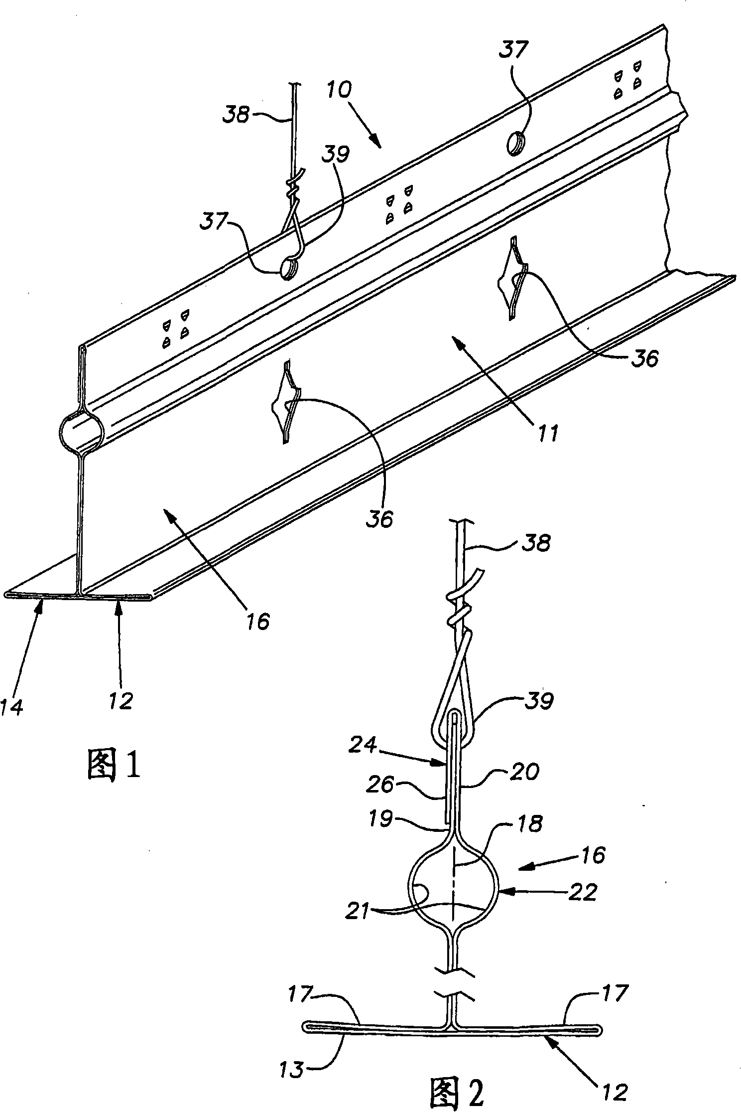
[0017] The grid tee 10 is preferably formed from a sheet of metal strip which may be galvanized or otherwise treated to resist corrosion. Preferably, the T-shaped piece 10 is made to have a cross section such as that shown in FIG. 2 using roll forming techniques known to those skilled in the art. Preferably, the central portion 12 of the metal strip 11 is painted before the metal strip is formed into a T-shaped section. The painted central part 12 forms the visible face 13 . The sheet metal strip 11 is folded back on two opposite sides of the visible face 13 to form a double flange 14 extending laterally on two opposite sides of a central plate or bar 16 . The inner layer 17 of the flange 14 extends from the outer end of the flange to a central imaginary plane 18, and preferably adjoins the outer layer or central portion 12 substantially across its entire width. The inner layers 17 of the flanges 14 meet at an imaginary plane 18 where the sheet metal strip is bent at right a...


PUM


Abstract

A roll-formed sheet metal tee for grid type suspended ceilings with the face of its flange integral with the stem and the layers of the stem fixed together for improved torsional strength. An upper region of the stem can have one or more of its layers folded to increase suspension wire breakout strength. A stiffening bulb is below suspension wire receiving holes so that a loop of the suspension wire through the tee has a narrow profile and thereby avoids interference with ceiling panels during their installation or removal.

Description

technical field [0001] The present invention relates to a suspended ceiling system and, more particularly, to an improved lattice tee. Background technique [0002] Suspended ceilings, widely used in commercial buildings, typically employ a rectangular grid system that supports recessed ceiling panels or tiles. This grid consists of regularly spaced carriages intersecting at right angles. These carriages are usually in the form of inverted T-pieces. These tees are typically hung from wires and the ceiling panels or tiles rest on the flanges of the tees. [0003] The design and manufacture of lattice T-pieces has been highly refined in the suspended ceiling production industry. Continuous efforts in improvement have resulted in the widespread acceptance of these ceiling systems in the construction industry. However, there are still challenges in improving the performance of the grid system and reducing its cost. Contents of the invention [0004] The present invention ...

Claims


Application Information

Patent Timeline
Patent Type & Authority Applications(China)
IPC IPC(8): E04B2/00
CPCE04B9/068E04C2003/0439E04C2003/0413Y10T29/49627E04C2003/046
Inventor 小詹姆斯·J·勒汉佩德·J·古尔布兰森马丁·E·利科扎尔
Owner USG INTERIORS INC
Why Eureka
Try Eureka