Electric up-down kitchen cabinet

A kind of cabinet and electric technology, applied in the direction of cabinets, kitchen cabinets, household appliances, etc., can solve the problems of shaking, shaking phenomenon, the inflexibility of double-layer storage trays, etc., to achieve the effect of flexible lifting

Active Publication Date: 2009-01-28
徐剑光 +1
View PDF1 Cites 11 Cited by
  • Summary
  • Abstract
  • Description
  • Claims
  • Application Information

AI Technical Summary

Problems solved by technology

[0003] In actual use, although the electric lifting cabinet with the above structure overcomes the inconvenient defect of accessing items in the wall-mounted hanging cabinet, it still has a disadvantage: because the double-layer storage tray only passes through it One side is connected with a chain or a sling to complete the ascent or descent of the storage tray, so the described double-layer storage tray is not only not flexible enough in the process of ascent or descent, but also has serious vibrations, especially when the storage tray When the center of gravity is unstable, the shaking phenomenon is more serious, which will eventually affect the normal use of the cabinet
[0004] In addition, although the above-mentioned utility model can stop the rotation of the motor through the limit switch, that is, stop the rising or falling of the storage tray, but because the speed of the storage tray remains constant during the process of rising or falling, when the fixing clip or When the storage tray touches the push rod of the limit switch, the storage tray will have a strong impact with the bottomless cabinet under the action of great inertia, causing a lot of noise. In serious cases, the storage tray or the bottomless cabinet will also be Damaged by strong impact

Method used


Image

  • Electric up-down kitchen cabinet
  • Electric up-down kitchen cabinet
  • Electric up-down kitchen cabinet

Examples


Embodiment Construction

[0018] The present invention will be further described below in conjunction with the drawings and specific embodiments:

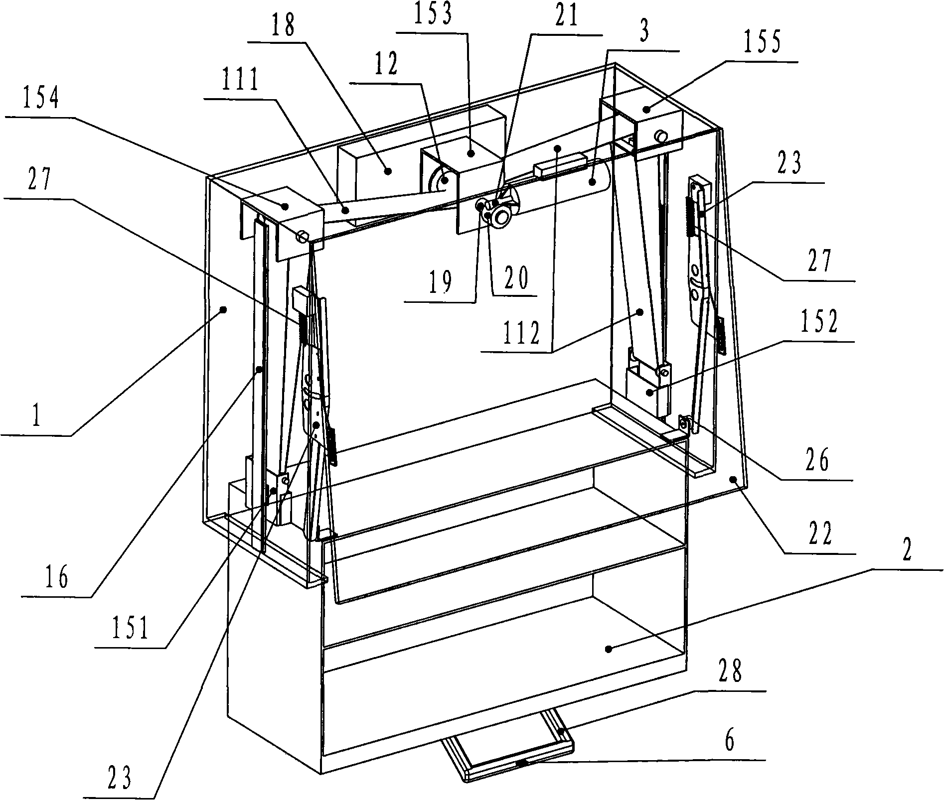
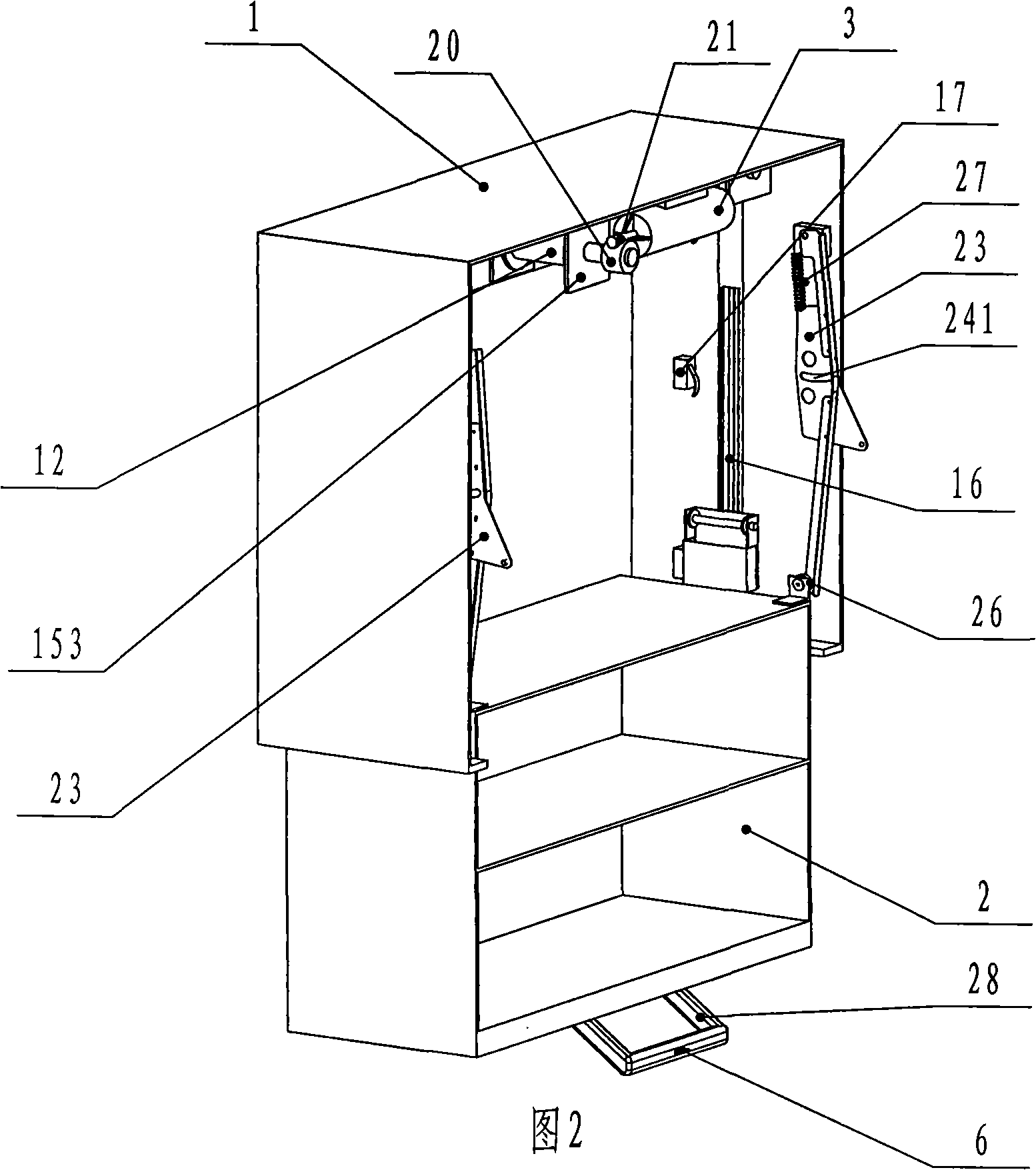
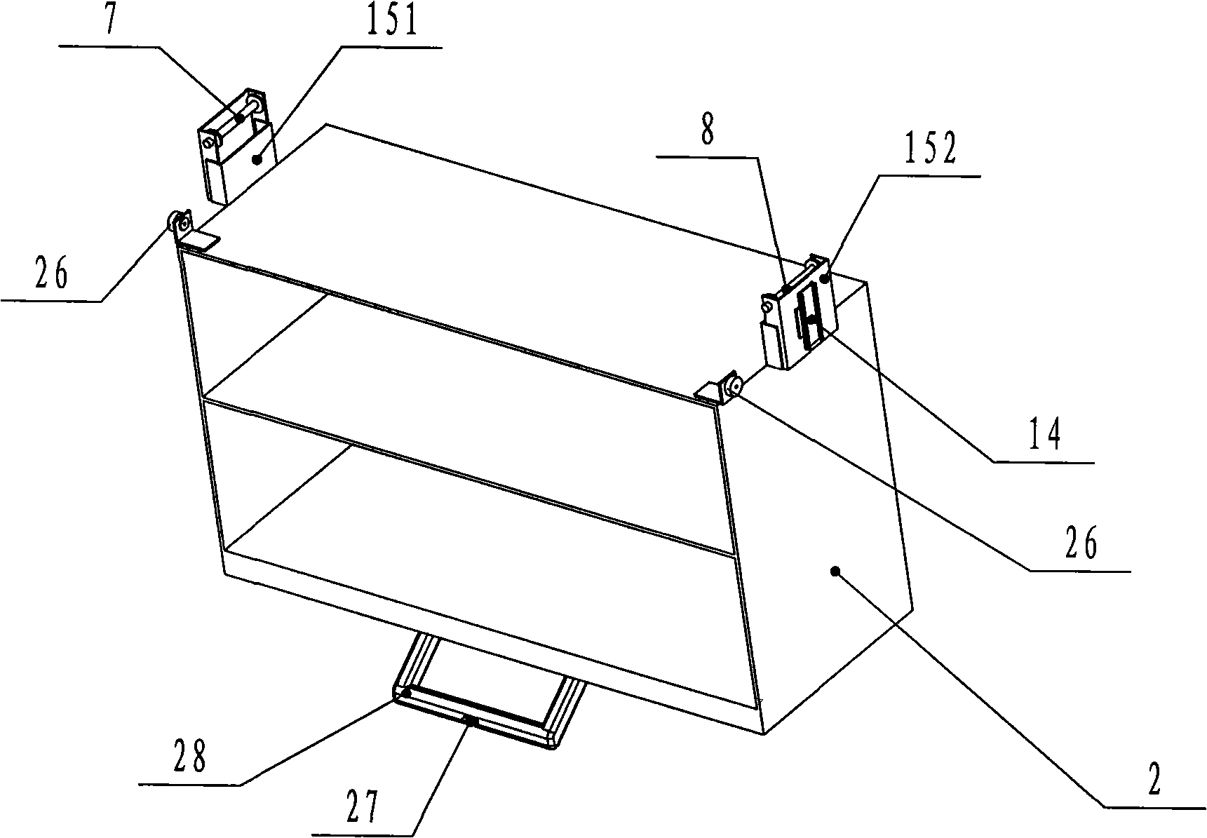
[0019] Such as figure 1 ,figure 2, image 3 , Figure 4 As shown in Fig. 5, the electric lifting cabinet of the present invention includes a bottomless cabinet 1, a storage cabinet plate 2 and a lift switch 6; the bottomless cabinet 1 is equipped with a motor 3 on the top; There is a lifting mechanism between the bottomless cabinet 1 and the storage cabinet plate 2; the bottomless cabinet 1 is provided with an upper limit switch 4 and a lower limit switch 5 on the right inner side wall; the lifting switch 6 is arranged in the storage The handle 28 at the bottom end of the cabinet 2 is electrically connected to the motor controller 18. In the present invention, the upper limit switch 4 and the lower limit switch 5 can be arranged on the left inner side wall or the right inner side wall of the bottomless cabinet 1 at the same time. The invention preferably arrang...


PUM


Abstract

The invention discloses an electric lifting cupboard which comprises a bottomless cupboard body (1), a cupboard tray (2), a motor (3), a lifting mechanism, an upper limit switch, a lower limit switch and a lifting switch (6); the lifting mechanism comprises a right movable pulley and a left movable pulley, a right static pulley, a left static pulley, a left leather belt (111), a right leather belt (112) and a driving pulley (12) that is arranged in the middle of the top of the bottomless cupboard body (1) and connected with the motor (3), wherein, the right movable pulley and the left movable pulley are respectively arranged at the two sides of the top of the cupboard tray (2); the right static pulley, the left static pulley, the left leather belt (111) and the right leather belt (112) are arranged at the two sides of the top of the bottomless cupboard body (1); one end of the left leather belt (111) and the right leather belt (112) is fixed on the driving pulley (12) at the same time, while the other end thereof respectively passes the right static pulley, the left static pulley, the right movable pulley and the left movable pulley and is fixedly arranged on a left fixing bar and a right fixing bar arranged beside the right static pulley and the left static pulley; the right movable pulley and the left movable pulley are movably matched with the inner wall of the bottomless cupboard body (1). The electric lifting cupboard has the advantages of flexible lifting and no dithering phenomenon happening during the processes of rising and falling.

Description

Technical field: [0001] The invention relates to a novel appliance used in a household kitchen, in particular to an electric lifting cabinet hung on the wall of the household kitchen. Background technique: [0002] The utility model patent with the authorized announcement number CN2770468Y discloses an electric lifting cabinet hung on the wall of a family kitchen. It includes a box-shaped bottomless cabinet body, which can be mounted on the side wall of the bottomless cabinet body through a motor and a lifting mechanism. The double-layer storage tray, upper limit switch, lower limit switch that lifts and lowers on the three-section slide rail, and the down button and the up button set on the control panel on the lower edge of the front of the cabinet for controlling the lifting and lowering of the storage tray. The lifting mechanism in the above-mentioned utility model adopts two similar structures. One is: the motor arranged on the top of the cabinet is connected to a gearbox; t...

Claims


Application Information

Patent Timeline
Patent Type & Authority Applications(China)
IPC IPC(8): A47B77/00A47B77/18
Inventor 徐剑光
Owner 徐剑光
Why Eureka
Try Eureka